 |
|||
|
|
|||
|
Page Title:
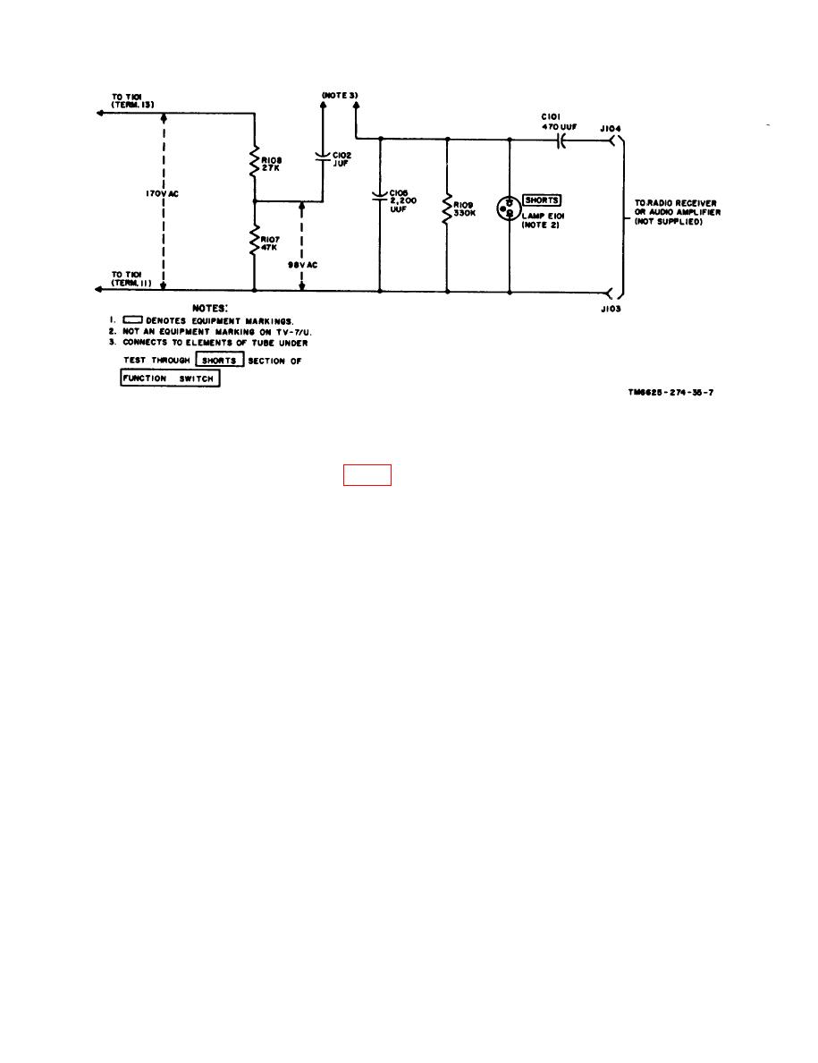
Figure 7. Simplified shorts and noise test circuit. |
|
||
| ||||||||||
|
|
 tion of the meter pointer is a measure of the
current will flow through R112; the
efficiency of electron emission of the tube.
remainder of the current will flow to
the slider arm of R127A, where the
c. The partial schematic diagram (fig. 8)
current will divide again. Some of
shows the various switch sections used, and the
the current will flow through resistor
contacts made, to test a type 5Y3WGTA elec-
R127A to the junction of R127A and
tron tube. Refer to the simplified circuit (fig.
R127B; the remainder of the current
9) for the operation of the circuit (d below).
will flow through the small resistance
d. When the polarity of the applied voltage
between the slider arm and the other
is such that terminal 34 is positive with respect
end of R127A, and through C103 and
to terminal 19, current flow will be as follows:
M101. The meter pointer will indi-
(1) Filament current will flow from ter-
cate the efficiency of electron emission
minal 19 of transformer T101 to the
of the tube. The current from C103
junction of R110 and pin 8 of the
and M101 will combine with the cur-
5Y3WGTA under test. The current
rent from R112, and will flow through
R127B to the junction of R127B and
will divide at this point. Some of the
R127A. The total current in the circuit
current will flow through R110; the
will flow through load resistor R106
r e m a i n d e r of the current will flow
to terminal 34 of T101.
through the filament-cathode of the
tube to the other side of R110. The
(3) When terminal 34 of T101 is negative
with respect to terminal 19, filament
total filament current will return to
current will flow from terminal 27 to
terminal 27 of the transformer.
the junction of R110 and pin 2 of the
(2) When pushbutton switch S110-7 is de-
5Y3WGTA under test. The current
pressed and an ac voltage is applied
will divide at this point. Some of the
between the plate and the cathode of
current will flow through R110; the
the tube, plate current will flow from
remainder of the current will flow
the cathode to the plate (pin 4) and
through the filament-cathode of the
through current limiting resistor R103
tube to the other side of R110. The
to pushbutton switch S110-7, where
total filament current will return to
the current will divide. Some of the
terminal 19 of the transformer.
12
|
|
Privacy Statement - Press Release - Copyright Information. - Contact Us |
