 |
|||
|
|
|||
|
Page Title:
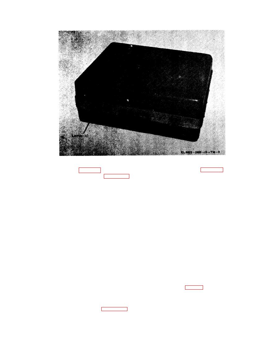
Figure 1-3. Case, Maintenance Accessory Kit CY-6774/ARM. |
|
||
| ||||||||||
|
|
 TM11-6625-2405-15
tender cables connect the front and rear sections
three breakout boxes as shown in figure 11 are
of respective disassembled radio sets. The separa-
similar in appearance. Each has a connector on
tion provides access to interior points for dynamic
o n e side of the box, three cables and a toggle
testing and adjusting while the radio set is con-
s w i t c h on the other side, and two sets of test
nected to Test Facilities Kit MK-994/AR.
points on top.
e. Termination box and associated cables ( f i g .
( 1 ) One set of test points (labeled A2J1)
1-8). The termination box and associated cables
is used to make measurements in the power and
a r e provided for testing of radio set audio cir-
control circuit lines to the radio set. The in-line
c u i t s . Proper termination for microphone and
test points also are connection points between the
h e a d s e t circuits is provided. A cable with a
cable to the rear of the radio set and the lines
U-93AL/U plug connects the termination box to a
from connector J1. Connector J1 accepts connec-
cable (terminated by a U92A/U jack) from Test
tion from Test Facilities Kit MK-994/AR which
Facilities Kit MK994/AR. Double banana jacks
is used for testing the radio set. Each test point
marked MIC and HDST provide connection to
is lettered with the respective pin numbers of the
t e s t equipments through the CX-12175/ARM or
jacks to correlate use with t e radio set technical
the CX-12176/ARM. The CX-12175/ARM has
manuals. By use of the toggle switch, input cur-
a d o u b l e b a n a n a plug at each end; the
r e n t can be metered at the two red test points
CX-12176/ARM has a double banana plug at
labeled D and D1.
one end and a BNC connector (UG-88/U) at the
(2) The other set of test points gives access
other end.
t o the connecting lines between the front and
rear sections of the radio set under test. The test-
a d a p t e r s are provided. The UG-1894/U (3 S U P-
point terminals are the connection points for the
plied) provides a tps-to-bnc connection, the UG-
w i r e s brought to the breakout box by the two
1 8 9 5 / U interconnects cables with Conhex con-
cables to the radio set halves. Figures 2-1, 2-2,
nectors, the UG-914/U is a straight-through bnc
a n d 2-3 show the breakout boxes connected to
c o n n e c t o r adapter, and the UG-1893/U accepts
d i s a s s e m b l e d radio sets. Each test point is let-
Conhex connectors in a tee connection. Specific
t e r e d with the respective pin numbers of the
use of the cornnectors is explained in test setup
jacks to correlate use with the radio set technical
instructions in the DS procedures sections of indi-
manuals.
vidual radio set maintenance manuals.
1-4
|
|
Privacy Statement - Press Release - Copyright Information. - Contact Us |
