 |
|||
|
|
|||
|
Page Title:
CONNECTOR UG-1870A/U REPLACEMENT (CONT) |
|
||
| ||||||||||
|
|
 TM 11-5995-208-24&P-1
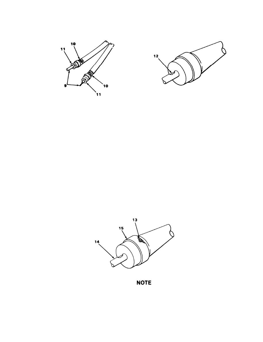
CONNECTOR UG-1870A/U REPLACEMENT (CONT)
NOTE
If there is a complete connector assembly already assembled on the opposite end of
cable, then a continuity check must be performed. A coaxial cable must have a male
contact at one end and a female contact at other end.
16. Slide proper center contact (9) over dielectric and under flared coaxial braid (10).
NOTE
If O-ring (11) stays with either contact, remove it before going to step 17.
Center conductor should be visible through contact solder and inspection hole (12)
before soldering.
17.
Using 60/40 solder, solder center conductor to contact (9) through solder and inspection
hole (12).
18. Remove excess solder from solder hole (12), and replace O-ring (11) if required.
Be sure that no strand of braid (13) is left outside center contact (14).
19. Trim coaxial braid (13) on each coaxial cable flush against flange (15) of center
contact (14).
3-25
|
|
Privacy Statement - Press Release - Copyright Information. - Contact Us |
