 |
|||
|
|
|||
|
Page Title:
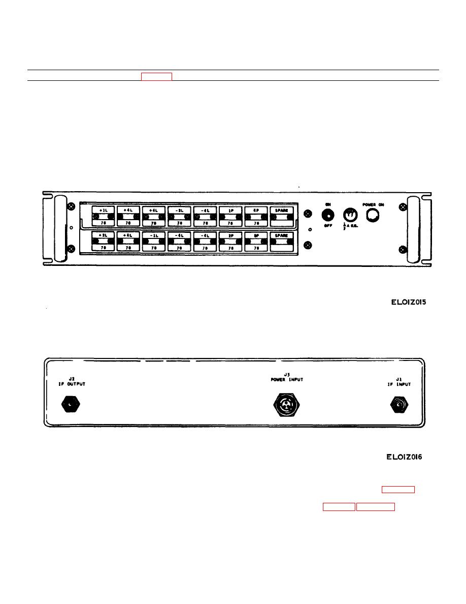
Table 3- 7. Equalizer, Group Delay CN-1425/MSC-46(V) Controls and Indicators. |
|
||
| ||||||||||
|
|
 TM 11-5895-833-12/NAVELEX 0967-LP-550-1010/TO 31R5-2TSC54-91
Table 3- 7. Equalizer, Group Delay CN-1425/MSC-46(V) Controls and Indicators.
Controls/indicator or connector (fig. 3-7)
Function
POWER-ON indicator lamp
Illuminates (white) to indicate presence of operating voltage.
ON/OFF toggle switch
Controls application of ac power to group delay equalizer.
IF input connector J1
Provides facility for connecting input signal.
IF output connector J2
Provides access to output of group delay equalizer.
115 VAC POWER INPUT connector J3
Power connection input plug.
+ 1L through + 4L modules
Inserts 1 to 4 nsec of positive linear equalization.
- 1L through - 4L modules
Inserts 1 to 4 nsec of negative linear equalization.
1P, 2P, 4P and 8P module
Inserts 1 to 8 nsec of parabolic equalization.
Spares
Provides a straight through path with no equalization to the
signal.
Figure 3-7 (1). Equalizer, Group Delay CN - 1425/MSC - 46(V), controls and indicators (sheet 1 of 2).
Figure 3-7 (2). Equalizer, Group Delay CN - 1425/MSV - 46(V), controls and indicators (sheet 2 of 2).
3-3. Time Base Patch Panel and Cabinet
patch panel and the cabinet are given in table 3-8, 3-9,
Interconnections and Test Points
and 3-10, respectively. Interconnections and test points
for unit 1 are given in table 3-9. Table 3-10 provides
The interconnections and test points for the time base
interconnections and test points for unit 2.
3-10
|
|
Privacy Statement - Press Release - Copyright Information. - Contact Us |