 |
|||
|
|
|||
|
Page Title:
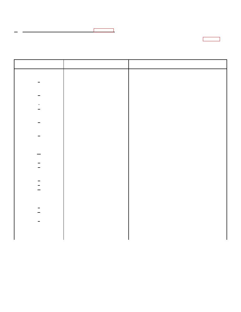
Table 2-4. Interface Cable Signal List |
|
||
| ||||||||||
|
|
 TM 11-5895-1179-13 * EE132-EA-OMP-010/E106 KY883 * TO 31S1-2GSC-161
b. Signal Connections for Normal Operation (figure 2-2). Connect the modem's input/output (I/O) cable assembly to
either A5A1J5 or A5A1J6 on the rear panel assembly of the encoder-decoder. (A5A1J5 and A5A1J6 are wired in parallel
so that either can be used.) The signals and their pin connections for the input/output connectors are listed in table 2-4.
Table 2-4. Interface Cable Signal List
Pin Letter
A5AlJ5,A5AlJ6
Signal
Description
A
+
}
B
-
ENC DATA
Transmit data to encoder
c
Shield
C
+
}
D
-
ENC R CLK
R clock to encoder
d
Shield
E
+
}
f
-
ENC 2R CLK
2R clock to encoder
e
Shield
F
+
}
G
-
ENC I DATA
Transmit symbols (Serial or I)
g
Shield
from encoder
L
+
}
M
-
ENC S CLK
4R clock from encoder in modes
k
Shield
B and C or 2R clock from
encoder in mode A
N
+
}
P
-
I SGN
Receive symbols (Serial or I
m
Shield
Channel) Sign Bit to decoder
R
+
Receive symbols (Serial or I
}
p
I MSB
Channel) most significant
n
Shield ,
bit (MSB) to decoder
S
+
Receive symbols (Serial or I
}
T
-
I LSB
Channel) least significant
g
Shield
bit (LSB) to decoder
v
+
}
w
DEC S CLK
4R clock to decoder in modes
HH
Shield
B and C or 2R clock to
decoder in mode A
JJ
+
}
x
-
DEC DATA
Decoded receive data from
Y
Shield
decoder
KK
+
}
z
DEC R CLK
R clock from decoder
AA
Shield
BB
+
}
CC
-
CH ER
Channel errors from decoder
LL
Shield
2-11
|
|
Privacy Statement - Press Release - Copyright Information. - Contact Us |