 |
|||
|
|
|||
|
Page Title:
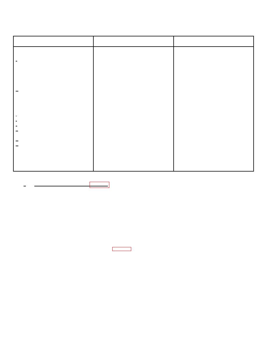
Table 2-4. Interface Cable Signal List-Continued |
|
||
| ||||||||||
|
|
 TM 11-5895-1179-13 EE132-EA-OMP-010/E106 KY883 * TO 31S1-2GSC-161
Table 2-4. Interface Cable Signal List-Continued
Pin Letter
A5AlJ5,ASAlJ6
Signal
Description
FF
+
}
GG
-
SYNC
Decoder Sync
t
Shield
H
Spare
J
Spare
U
Spare
V
Spare
Y
Spare
u
Spare
X
Spare
W
Spare
h
Ground
K
Not used
j
Not used
i
Ground
r
Ground
s
Ground
Z
Not used
b
Not used
a
Ground
DD
Not used
EE
Not used
MM
Ground
NN
Not used
PP
Ground
c.
Monitor Connector A5A1J7 (figure 2-2). A monitor connector A5A1J7 is provided on the rear panel assembly for
remote control operation and for interface with external monitoring systems. The logic levels of the monitor signals are as
follows:
Driver Outputs
Logic zero
0 to +0.4 Vdc
Logic one
+2.4 to +5.5 Vdc
Receiver Inputs
Logic zero
0 to +0.8 Vdc
Logic one
+2.0 to 5.5 Vdc or open circuit
(1) All signals are provided with transistor-transistor logic (TTL) levels, with the exception of the contact closure
which is either an open circuit (no fault condition) or a short circuit (malfunction conditions). (2) The signals and their pin
connections for the monitor connector are listed in table 2-5.
2-12
|
|
Privacy Statement - Press Release - Copyright Information. - Contact Us |