 |
|||
|
|
|||
|
Page Title:
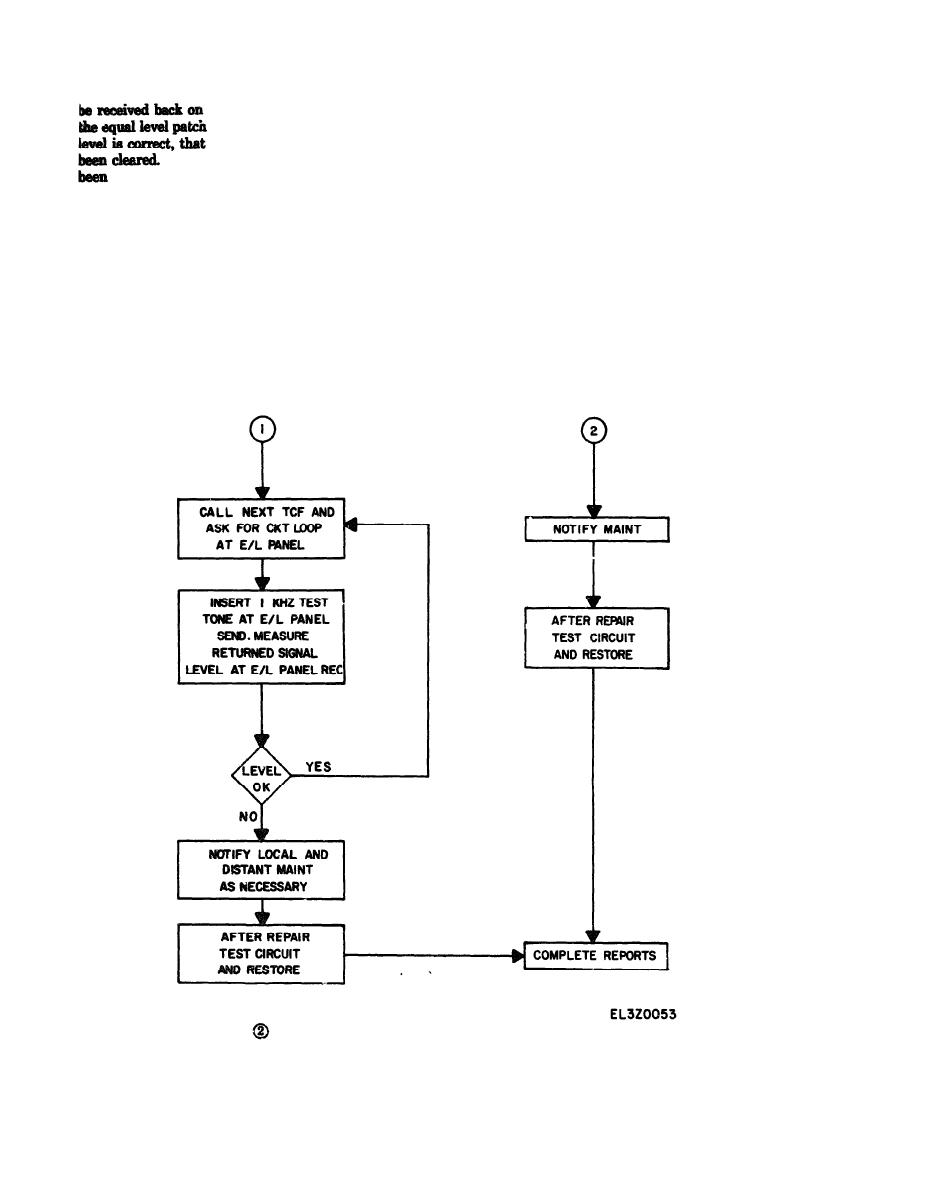
Figure 4-92 . Vf subscriber circuit loop-back method, fault isolation flow chart (sheet 2 of 2) |
|
||
| ||||||||||
|
|
 TM 11-5895-1012-10
that channel's receive circuit on
the reason for the fault and location, and complete sta-
panel at a level of 0 dBm. If the
tion record% in accordance with established pro=
leg of the defective channel has
cedures.
If the level is not correct, the fault has
isolated between the two TCF's and the trouble
lation Procedures
can be turned over to maintenance personnel.
(4) If the tone looped back is received at the
a. Open Circuit Condition. The station Technical
proper level, the distant TCF is requested to remove
Control Facility is notified by a connected telegraph
the loop back patch and the next TCF further toward
subscriber that incoming traffic has been interrupted
the signal source is requested to perform a similar
and that the printer has started to run open.
patch. Again the local TCF inputs a 1000 Hz tone at
Reference to the circuit layout record card indicates
0 dBm and measures the level of the looped back tone.
that the subscriber circuit is connected by cable to a
Following this procedure, trouble can be isolated be-
nearby military installation. The most likely reason
tween any two equal level patch panels in the channel.
for the condition reported is a break in the dc loop
(5) When the fault has been located in the de-
cawed by failure of the loop battery, an open connec-
fective circuit, the tasks is turned over to maintenance
tion at the subscriber terminal, a defect in the cable, or
personnel to clear the trouble. After the fault has been
an electrical failure of the receiving equipment.
(1) Loop Battery Check. The Technical Controller
cleared, restore the circuit to its normal path, obtain
|
|
Privacy Statement - Press Release - Copyright Information. - Contact Us |
