 |
|||
|
|
|||
|
Page Title:
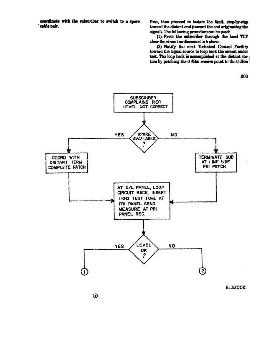
Figure 4-91. Vf subscriber circuit loop-back, fault isolation flow chart (sheet 1 of 2) |
|
||
| ||||||||||
|
|
 TM 11-5895-1012-10
(15) After the fault has been cleared, remove any
patches which have been established and complete sta-
tion records in accordance with established proce-
dures.
c. Fault Isolation of a VF Subscriber Circuit by the
Loop-Back Method. This procedure followed is outlined
in flow-chart fashion in figure 4-9. The Technical
Controller is notified by a local subscriber that the cir-
send point of the same channel under test at the equal
cuit level is not correct. A spare channel is available
level patch panel.
and the circuit is patched over onto the spare circuit so
(3) The local Technical Controller inputs a 1
that the normal path can be available for out-of-service
Hz test tone on the send circuit at a level of 0 dBm at
testing. The basic procedure is to clear the local station
the equal level patch panel. The same test tone should
Vf subscriber circuit loop-back, fault isolation flow chart (sheet 1 of 2)
|
|
Privacy Statement - Press Release - Copyright Information. - Contact Us |