 |
|||
|
|
|||
|
Page Title:
Universal Digital Patch Panel,Programs |
|
||
| ||||||||||
|
|
 TM 11-5895-1012-10
send with timing from an external
standard to both sending and receiving devices.
(5) The patch panel also incorporates a special
circuits utilizing either an external
function for
timing standard or timing from a receiving device to a
sending device. When a transmitted signal is to be
M3 to M2
receiving portion of the same
patched back
D3 to E2
purposes, a problem would nor-
equipment for
M3 to J3
mally arise. Since external timing is necessarily intro-
H3 to E1
duced on the line side of a jack field, a line-send-to-line-
L1 to J1
l (back to back) patch required to perform
F2 to F3
ve test for equipment external to the TCF con-
H3 to N3 (Not shown)
two timing signals (one injected into the send
Al to H1 (Not shown)
field and one received on the incoming line). Con-
A2 to M1 (Not shown
versely, an equipment send-to-equipment-receive (back
E3 to K1 (Not shown)
to back equip) patch required to perform the test for
H3 to N3 (Not shown)
equipment internal to the TCF contains no timing sig-
C3 to D1 (Not shown)
nal. When timing is sent from a receiving device to a
C3 to K3 (Not shown)
the same problem can occur (i.e., two
on a back to hack line and none on a
(2) When a patch cord plug is inserted into the
LINE jack, the following connections are made.
uip).
A push button "back-to-back" switch allows the remov-
Terminal
al of one of the two timing signals present in a back to
T
line patch and the introduction of timing in a
to-back equip patch. An indicator light as well as
T1
switch position indicates the activation of this func-
R1
External timing
tion in all cases.
(3) When a patch cord plug is inserted into the
(6) The signal common "ring" lead of an interrupt-
EQUIP jack, the following connections are made.
ed signal is never left open. It may be supplied DC
Terminal
ground or another program elected termination.
T
R
External timing
T1
To plugged line equipment
Programs
R1
To plugged line equipment
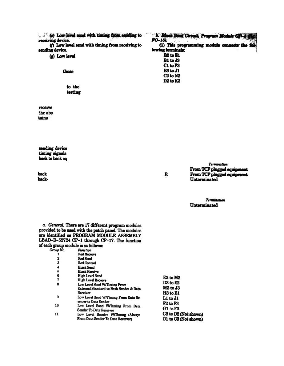
c. Black Receive Circuit, Program Module GP-5
(fig. FO-16).
(1) This programming module connects the fol-
lowing terminals:
B2 to E1
B1 to J3
C1 to F3
B3 to J1
C2 to N2
D2 to K3
|
|
Privacy Statement - Press Release - Copyright Information. - Contact Us |
