 |
|||
|
|
|||
|
Page Title:
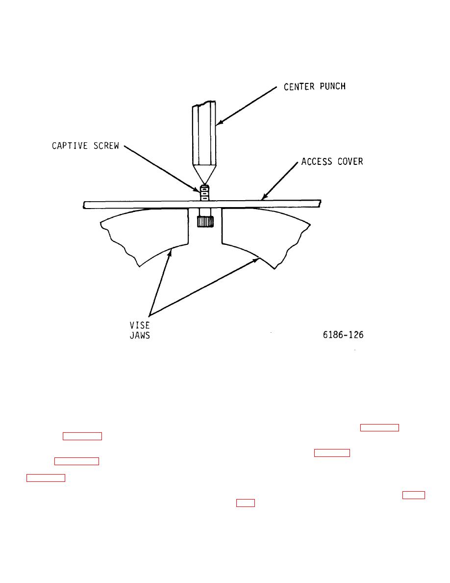
Figure 6-15. Captive Screw Removal Diagram |
|
||
| ||||||||||
|
|
 T.O. 31W2-2GSC24-2
TM 11-5805-688-14-1
NAVELEX 0967-LP-545-3010
Figure 6-15. Captive Screw Removal Diagram
from access cover. Remove cover from vise.
7. Lightly squeeze installation tool lever,
causing fastener ferrule to flare into countersink in
3. Grasp remaining portion of fastener with
access cover.
slip-joint pliers, and gently rock fastener back and forth
until it is released from access cover.
8. Draw installation tool knob to open position,
causing tool to unthread from installed fastener. A
4. Insert replacement fastener through access
properly installed fastener is shown in figure 6-16, view C
cover hole (figure 6-16, view B).
6-72. Replace captive retaining screws attached to the
5. Draw knob of installation tool P/N 29-47-
power supply heat sink (figure 6-3) as follows:
101-10 (figure 6-16, view A) to open position, and
position nose of tool against threaded end of fastener
1. Place power supply, heat sink down, on a
workbench or other suitable flat surface.
6. Return knob of installation tool to closed
2. In a manner similar to that shown in figure
position, causing tool to thread onto screw.
from heat sink.
6-52
|
|
Privacy Statement - Press Release - Copyright Information. - Contact Us |