 |
|||
|
|
|||
|
Page Title:
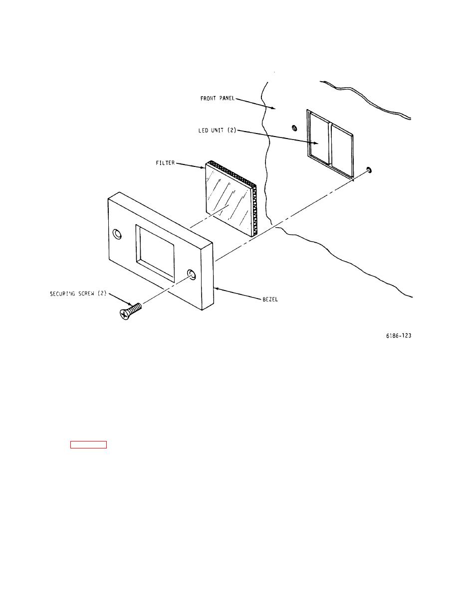
Figure 6-4. LED Element Replacement |
|
||
| ||||||||||
|
|
 T.O. 31W2-2GSC24-2
TM 11-5805-688-14-1
NAVELEX 0967-LP-545-3011
Figure 6-4. LED Element Replacement
Blower replacement requires free
3. When fan comes to a full stop, carefully lift
access to the rear of the multiplexer
blower panel from chassis and disconnect the blower's
set chassis. The chassis may have to
partial-turn power connector. Set panel on a bench or
be extended and rotated on its
other suitable work surface.
mounting slides before blower
replacement is started.
4. Loosen but do not remove three screws securing
blower to blower panel.
1. Loosen 10 captive fasteners securing cooling
blower panel (figure 6-2) to rear of multiplexer chassis.
5. Align three flat-sided nuts on blower retaining
screws so that flat side of each is parallel with blower
2. Tilt top of blower panel out from chassis until
housing.
electrical interlock is actuated. Interlock actuation is
evidenced by an audible and visible slowing of the
cooling blower fan.
6-26
|
|
Privacy Statement - Press Release - Copyright Information. - Contact Us |
