 |
|||
|
|
|||
|
Page Title:
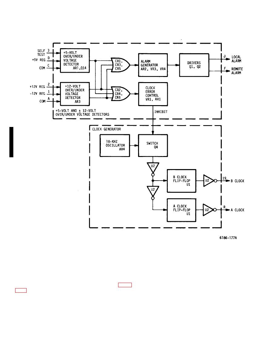
Figure 5-46. 12-volt Regulator Card, Clock Generator and Over/Under Voltage Detector Circuits - Block Diagram |
|
||
| ||||||||||
|
|
 T.O. 31W2-2GSC24-2
TM 11-5805-688-14-1
NAVELEX 0967-LP-545-3010
Figure 5-46. 12-volt Regulator Card, Clock Generator and Over/Under Voltage Detector Circuits - Block Diagram
5-627. Basically, the four identical +5-volt regulator
two voltages are applied to a voltage comparator. An
circuits are similar to the 12-volt regulator circuit
increase in either voltage causes the output voltage from
the voltage comparator to the error amplifier to increase.
discussed in this paragraph. Therefore, the +5-volt
A decrease in either voltage causes the output voltage
regulator circuits are not discussed in detail in the block
diagram discussion. The 12-volt regulator circuit (figure
from the voltage comparator to the error amplifier to
decrease. An increase in voltage to the error amplifier
causes a higher (more positive) threshold voltage to be
generate control signals as necessary to regulate the two
applied to the high-speed comparator.
outputs within 1.0 percent of +12 and -12 volts. The
Change 2 5-170
|
|
Privacy Statement - Press Release - Copyright Information. - Contact Us |