 |
|||
|
|
|||
|
Page Title:
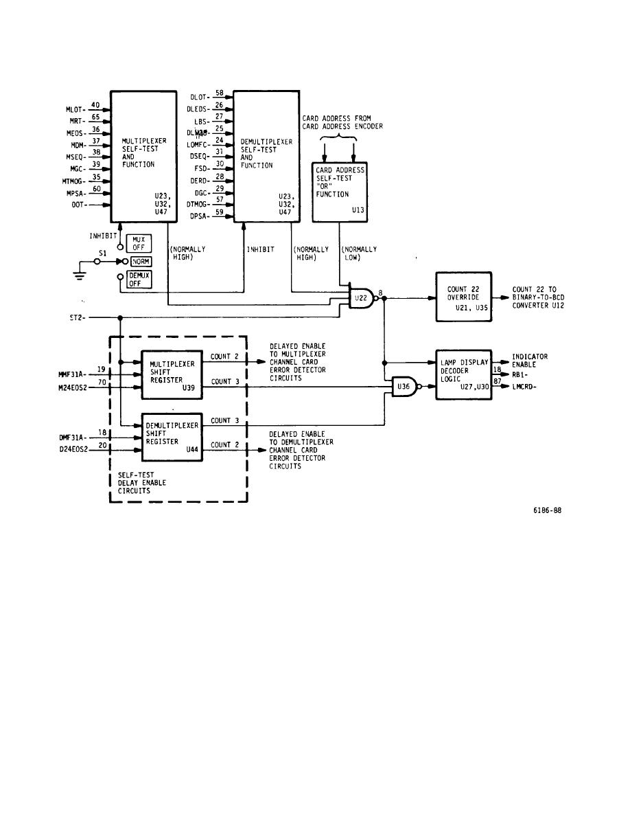
Figure 5-44. Display Card, Secondary Diagnostics - Block Diagram |
|
||
| ||||||||||
|
|
 T.O. 31W2-2GSC24-2
TM 11-5805-688-14-1
NAVELEX 0967-LP-545-3010
Figure 5-44. Display Card, Secondary Diagnostics - Block Diagram
At the end of the next word time (second clock), when
shift registers remain high until completion of the self-test
signal M24EOS2 is produced, the shift register is clocked
mode. When signal ST2 goes low, both shift registers
and count 2 becomes a 1. At this time, the multiplexer
are reset and counts 2 and 3 become 0 and AND gate
and demultiplexer channel card error detector cir- cuits
U36 is inhibited. Logic circuits in the primary diagnostic
are enabled.
When the next (third clock) signal
circuits prevent the 0 from count 2 from inhibiting the
M24EOS2 occurs, the shift register is clocked again and
multiplexer and demultiplexer channel card error detector
count 3 becomes a 1. At this time, an enable is applied
circuits when the equipment is not in the self-test mode.
to one input of AND gate U36. Counts 2 and 3 from the
5-159
|
|
Privacy Statement - Press Release - Copyright Information. - Contact Us |