 |
|||
|
|
|||
|
Page Title:
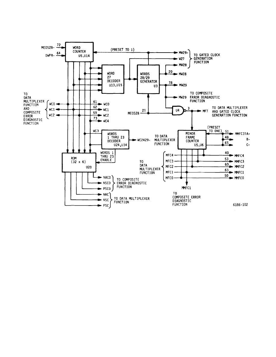
Figure 5-22. GC/DM Card, Format Generation Circuits - Block Diagram |
|
||
| ||||||||||
|
|
 T.O. 31W2-2GSC24-2
TM 11-5805-688-14-1
NAVELEX 0967-LP-545-3010
Figure 5-22. GC/DM Card, Format Generation Circuits - Block Diagram
5-313. At word count 27, the word 27 decoder
5-314. When signals MEOS2B and MW29 are present,
generates word 27 that is applied to the words 28 and 29
AND gate U4 generates minor frame transition signal
generator once each minor frame. Words 28 and 29 are
MFT that increments the minor frame counter once each
clocked out of the generator by end-of-scan signal
minor frame. Signal MFT is also applied to the gated
MEOS2B from the sequencer card. Word MW29- is
clock function on the card. The minor frame counter
applied to the data mux function routed to the OEG card,
produces 5-bit minor frame count signals MMFCO
and is also used to preset the word counter to a count of
through MMFC4 that sequentially count from minor
1. Signal word 29 is applied to the word 29 activity
frame counts 1 (MMFC1) through 31 (MMFC31). The
detector in the diagnostic circuits and is also routed to
counter also generates three sets of minor frame 31
the OEG card. Word 28 is routed to the sequencer card.
signals MMF31A, MMF31B, and MMF31C that are
routed to the channel card locations in the multiplexer.
5-80
|
|
Privacy Statement - Press Release - Copyright Information. - Contact Us |
