 |
|||
|
|
|||
|
Page Title:
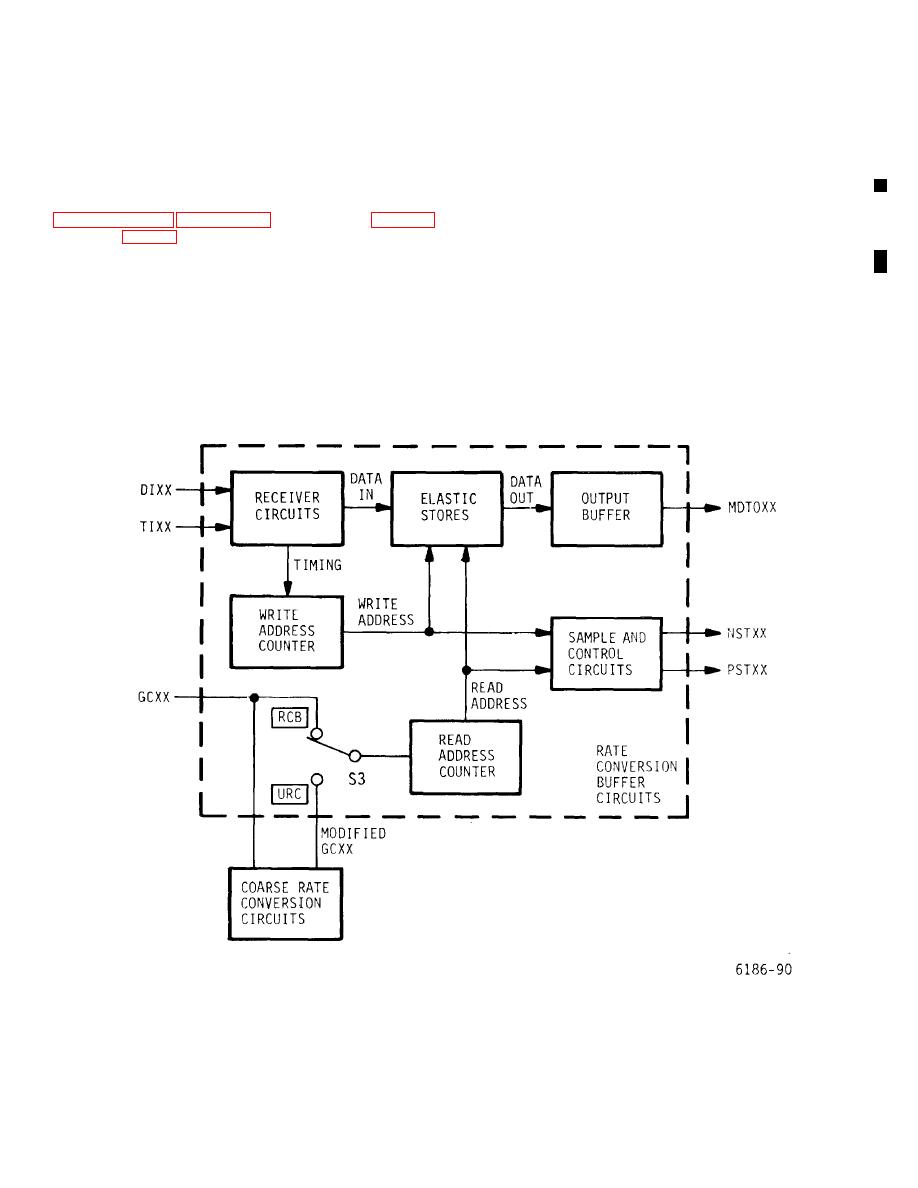
Figure 5-11. RCB Card - Simplified Block Diagram |
|
||
| ||||||||||
|
|
 T.O. 31W2-2GSC24-2
TM 11-5805-688-14-1
NAVELEX 0967-LP-545-3010
synchronized to the multiplexer timing, and then, as
the card is programmed is determined by the relationship
synchronous data, are routed to the GC/DM card, where
of the applied data bit rate as compared to the internal
=
multiplexer timing rate in the formula RC KRp
the digital data are multiplexed into the multiplexer output
serial data stream. The block diagram discussions in
where
11 through 5-14. The detailed circuit discussions are
RC= applied channel data rate (between 50 bps and 3
based on the RCB card logic diagrams in the circuit
Mbps) within 250 ppm of KRp
diagrams manual.
5-168. BLOCK DIAGRAM DISCUSSION.
K = number of used ports strapped together to service
an active channel
5-169. General. The RCB card can be operated in one
of two modes. The mode of operation is selected by
Rp = port rate at which each used port is sampled.
setting switch S3 to the URC or the RCB position. The
mode of operation to which
Figure 5-11. RCB Card - Simplified Block Diagram
Change 2 5-39
|
|
Privacy Statement - Press Release - Copyright Information. - Contact Us |