 |
|||
|
|
|||
|
Page Title:
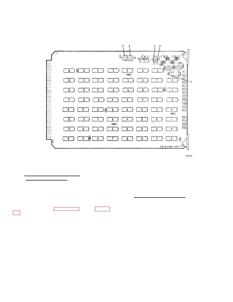
Figure 3-20. FS Card - Switch Location Diagram |
|
||
| ||||||||||
|
|
 T.O. 31W2-2GSC24-2
TM 11-5805-688-14-1
NAVELEX 0967-LP-545-3010
Figure 3-20. FS Card - Switch Location Diagram
3-91. DISPLAY CARD (P/N 61864050)
to the MUX OFF or DEMUX OFF position as applicable.
SETUP PROCEDURES.
This will inhibit diagnostic error indications from the
portions of the multiplexer set not being used. Install the
3-92. The display card is located in slot 22 of the
display card in slot 22 of the DEMULTIPLEXER row.
MULTIPLEXER row. Set up the display card as follows:
3-93. THERMAL ALARM OPTIONS.
1. If both the multiplexer and demultiplexer portions of
3-94.The multiplexer set has alarm circuits that activate
the multiplexer set are being used, i.e., overall
when the operating temperature within the set exceeds
configuration is duplex (paragraph 3-7), set S1 (figure 3-
specified limits. Upon activation, the alarm circuits are
set up to perform one of the two following optional
functions: (1) light the front panel TEMPERATURE
2. If either the multiplexer or the demultiplexer portion of
indicator, cause a remote alarm indication to appear at
the multiplexer set is not being used, set S1
connector
3-53
|
|
Privacy Statement - Press Release - Copyright Information. - Contact Us |