 |
|||
|
|
|||
|
Page Title:
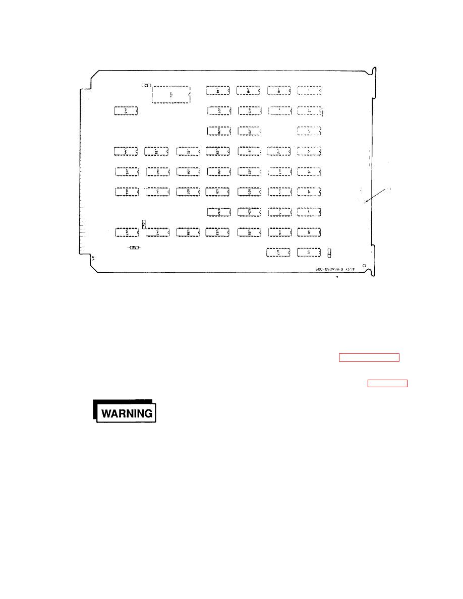
Figure 3-22. Display Card - Switch Location Diagram |
|
||
| ||||||||||
|
|
 T.O. 31W2-2GSC24-2
TM 11-5805-688-14-1
NAVELEX 0967-LP-545-3011
Figure 3-22. Display Card - Switch Location Diagram
J66, and cause the multiplexer set power supply to
panel. Turn multiplexer power
automatically shut down; and (2) light the front panel
off and disconnect power cord
TEMPERATURE indicator and cause a remote alarm
from power source before
indication to appear at connector J66.
removing front panel assembly.
3-95. In option 1, the multiplexer set ceases to process
3-96. If option 2 is desired, remove power, remove
input/output data until the cause of the overtemperature
the front panel assembly (paragraph 6-23), and
situation is corrected. The multiplexer set is initially
carefully remove the bare wire jumper soldered
manufactured with option 1 installed.
between terminals E24 and E25 of front panel
board A2A1 (P/N 61861028) (refer to figure 3-23 for
terminal locations). Option 1 can be reinstalled by
soldering a jumper between terminals E24 and E25.
Dangerous
voltages
are
present
within
the
front
Change 1 3-55
|
|
Privacy Statement - Press Release - Copyright Information. - Contact Us |