 |
|||
|
|
|||
|
Page Title:
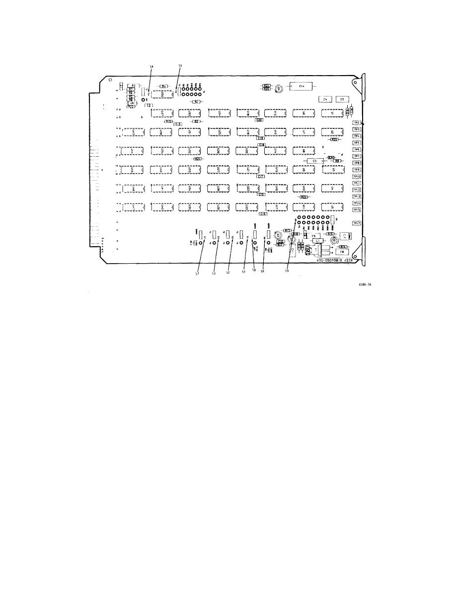
Figure 3-13. TE/TR Card - Switch Location Diagram |
|
||
| ||||||||||
|
|
 T.O. 31W2-2GSC24-2
TM 11-5805-688-14-1
NAVELEX 0967-LP-545-3010
Figure 3-13. TE/TR Card - Switch Location Diagram
3. Set S8 to the NORM position.
position. If S1, S2, and S3 are set to the TE position,
proceed to step 5. If S1, S2, and S3 are set to the TR
position, proceed to step 6.
NOTE
5. Multiply the number of ports (K) assigned to
Failure to set S8 to the NORM
the channel as indicated on sheet 1 and the port rate
position will inhibit the display of any
(Rp) entered on sheet 2 of the worksheets. Divide the
errors detected by the TE/TR card
product (KRp) by 3, and set S5 on the TE/TR card to the
diagnostic circuits.
computed KRp/3 value. This completes the setup of the
TE/TR card for the TE mode of operation.
4. Refer to sheet 1 of the worksheets and note if
the CARD TYPE TE/TR block is marked TE or TR. Set
card switches S1, S2, and S3 to the indicated TE or TR
3-36
|
|
Privacy Statement - Press Release - Copyright Information. - Contact Us |
