 |
|||
|
|
|||
|
Page Title:
Connect harness 11673835 to the driver's master control panel. |
|
||
| ||||||||||
|
|
 TB 9-2350-257-20-1
STEP 5
Connect harness 11673835 to the driver's master control
b. If 22 to 26 VDC does not exist, troubleshoot
panel.
Circuit 10 per the technical manual
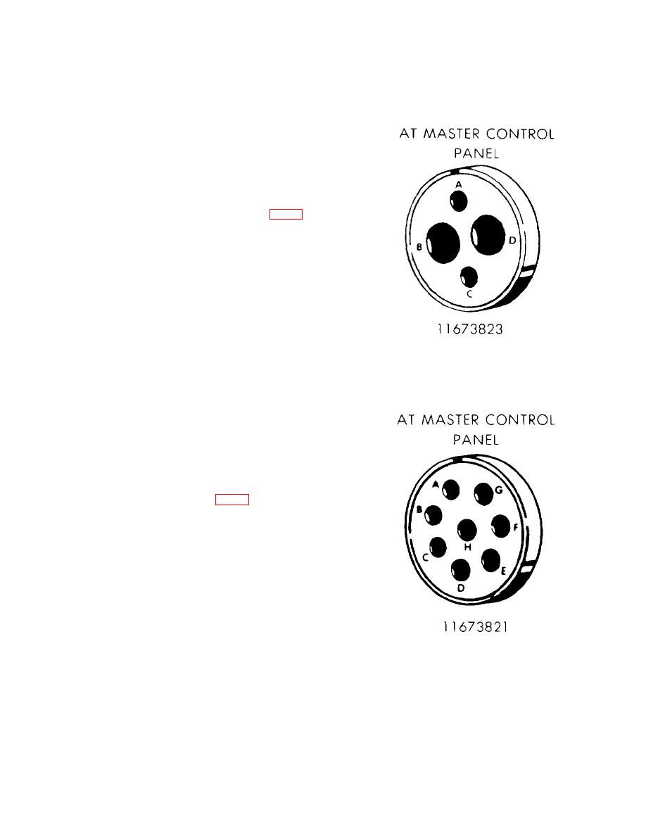
Disconnect harness 11673823 connector (Circuit 10)
from the driver's master control panel
Place MASTER BATTERY switch to the ON position.
Measure voltage 22 to 26 VDC at harness 11673823
connector (Circuit 10) on socket B (+) to vehicle chassis
(GROUND) a. If 22 to 26 VDC exists, proceed to step 6
STEP 6
Place MASTER BATTERY switch to OFF position.
b. If continuity does not exist, repair harness
(11673821) (11655751).
Remove driver's master control panel. Refer to TM 9-
2350-257-20-1.
Check continuity harness 11673821 (11655751)
connector socket C (Circuit 1A) at the driver's master
control panel to the harness 11673821 (11655751)
terminal at the fuel pump switch Packard connector.
a. If continuity exists, proceed to step 7.
10
|
|
Privacy Statement - Press Release - Copyright Information. - Contact Us |