 |
|||
|
|
|||
|
|
|||
| ||||||||||
|
|
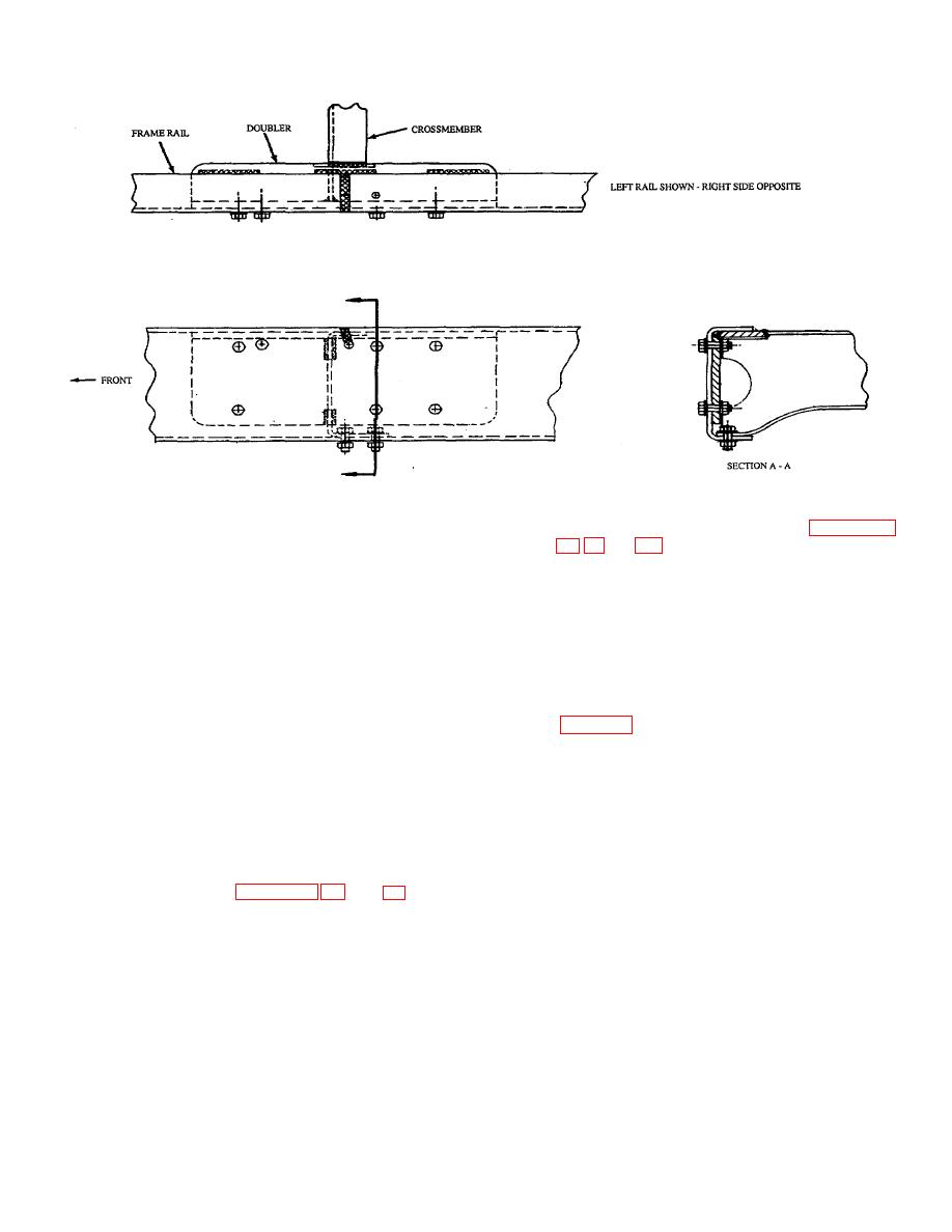 TB 9-2300-247-40
Figure 45. Repair at Crossmember (Upper Flange)
b. Fabricate doubler plate as shown in Figures 42,
NOTE
The
exact
doubler
location
c.
Bevel the doubler at the gap to a 450 angle.
determines the length of the cutout in
the trapezoid plate.
d. Securely bolt the doubler to the plate using new
No. 8 UNF bolts, washers, and locknuts. Torque
60.
Repair Procedure
bolts in accordance with appendix E of the
appropriate vehicle TM.
WARNING
e. Secure doubler to the rail and repair as shown in
Use Only effective chip guarding
equipment, protective equipment and
protective clothing (goggles, shields,
f.
Thoroughly clean repaired
surfaces
and
gloves aprons, etc when doing any
surrounding area of repair.
drilling, grinding, or welding. Failure
to follow this warning could result in
g. Prime and paint repair area and surrounding
injury to personnel.
surfaces as specified in TM-43-0139.
a. Using an oxyacetylene torch, provide cutouts in
61.
Defect. Cracks at jounce bracket requiring
the trapezoid plate with a maximum 5/32-inch
cutouts of portions of the trapezoid plate to accept the
gap as shown in Figures 47, 48, and 49 which
doubler flange and the addition of spacer.
specify the fabrication of doubler plates and
repairs to defective trapezoidal areas.
40
|
|
Privacy Statement - Press Release - Copyright Information. - Contact Us |
