 |
|||
|
|
|||
|
|
|||
| ||||||||||
|
|
 TM 11-6625-667-45
tual reading will be less than if taken with the
5.1-8. Isolating Trouble Within Stage
o h m m e t e r on the R x 1 0 0 r a n g e . W h e n i n
a. General. When trouble has been local-
d o u b t about the result of resistance measure-
ized to a transistor stage during troubleshoot-
ments, check a known good equipment of cor-
ing (para 5.1-7), isolate the defective part by
r e c t readings. The readings in b b e l o w w e r e
v o l t a g e measurements or resistance measure-
taken with each module removed from the
ments using the figure referenced in the note or
equipment. First measure between the base and
t h e Corrective measures column of the chart.
the emitter and between the base and the col-
For integrated circuit trouble isolation, refer to
l e c t o r with the positive ohmmeter lead con-
c below.
nected to the base; then measure between the
CAUTION
base and the emitter and between the base and
Carefully follow instructions and ob-
the collector with the negative ohmmeter lead
serve notes on voltage and resistance
connected to the base.
diagrams. Carelessness may cause
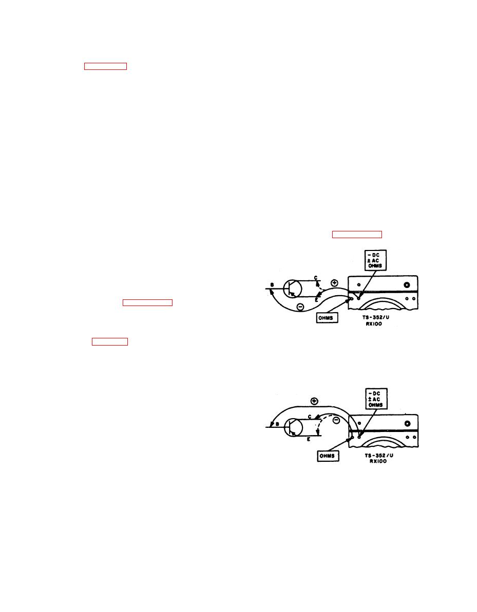
b. In-Circuit Transistor Resistance Charts.
m o r e troubles in the equipment and
Listed in the charts ((1) and (2) below) are
make the troubleshooting job more
r e s i s t a n c e measurements taken of the emitter
d i f f i c u l t . Do not remove or insert a
and collector with the transistors connected in
t r a n s i s t o r or integrated circuit ele-
t h e circuit. The measurements are made with
ment with voltage applied, to the cir-
M u l t i m e t e r TS-352B/U. These readings will
cuit. Do not perform resistance meas-
be valid only if the same type of ohmmeter is
u r e m e n t s of integrated circuit.
used and polarity and range scales are strictly
a d h e r e d to. Refer to figure 5.1-6 for the test
b. Transistor Testing. Since the transistors
setup.
are wired in the circuit, every effort should be
m a d e to troubleshoot the equipment without
physically unsoldering and removing the tran-
sistors.
c . Integrated Circuit Testing. Faulty inte-
grated circuits may be isolated by oscilloscope
s i g n a l tracing; figures 5.1-3 and 5.1-9 illus-
t r a t e the signal conditions at each applicable
pin.
d . W i r i n g D i a g r a m s . Use the wiring dia-
A. FORWARD
g r a m s (fig. 8-43, 8-44, and 8-45) to circuit
trace and isolate the fault part.
5.1-9. Analysis of Measurements
For an interpretation of readings when taking
t h e voltage and resistance measurements, re-
f e r to TB SIG 357.
a. In-Circuit Transistor Resistance Measure-
elements connected across the junction of any
transistor (base-emitter or base-collector), con-
sider polarity of the ohmmeter and try meas-
u r e m e n t s with the ohmmeter connected one
way; then reverse the leads. Also, consider that
different values of resistance will be obtained
with the ohmmeter on different ranges; for ex-
B. REVERSE
ample, if the transistor junction, or a resistor
TM6625-667-35-89
plus the transistor junction, is measured in the
Figure 5.1-6. PNP transistor resistance
forward direction of the R X 10 range the ac-
measurements
Change 1
5.1-17
|
|
Privacy Statement - Press Release - Copyright Information. - Contact Us |
