 |
|||
|
|
|||
|
|
|||
| ||||||||||
|
|
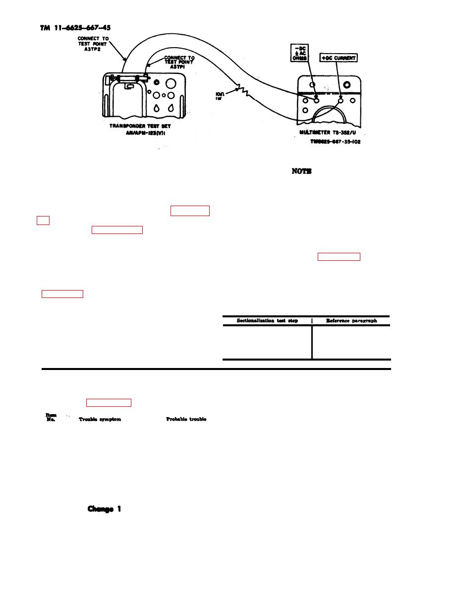 Figure 5.1-2. Current limiting measurements.
5.1-7. Localizing Troubles
Test setup and conditions should be
a. General. The troubleshooting charts (d,
as specified during the step in the
e, and f below) outline procedures for local-
sectionalization test where the trou-
izing troubles to a stage within the respective
ble was noted.
module. Schematic diagrams are in figures 8-
c. Troubleshooting Chart Location. The ap-
are located in figures 8-43, 8-44, and 8-45.
plicable troubleshooting chart is located by re-
Refer to b below before using the trouble-
ferring to the following chart and finding the
shooting charts.
sectionalization test step (para 5.1-6d where
b. Use. of Troubleshooting Charts. A trou-
bleshooting chart is provided for each module
the trouble was observed. The second column
or subassembly. Selection of the applicable
of the chart refers to the applicable paragraph
one is based on the sectionalization test step
containing
the applicable troubleshooting
chart.
To locate the troubleshooting chart covering
the probable faulty module, refer to c below.
Then find the description of the observed
symptom in the Trouble symptom column of
1
5.1d
5.1-6e
2 and 3
the referenced chart. Take the corrective meas-
4 and 5
5.1-6e
ures recommended in the Corrective measures
5.1-6f
6 and 7
column.
d. 6-Volt Regulator Module As Troubleshooting.
NOTE
Refer to figure 5.1-5 for socket voltages and resistances.
Corrective measurment
Adjustment
Adjust control A3R24 for normal
Improper voltage at test
1
indication. If adjustment does
point A3TP1.
not correct trouble, refer to
2 below.
Isolate improper operating stage
Note. Due to interaction of
2
Adjustment does not cor-
using voltage and resistance
stages systematic check of each
rect improper voltage
diagram.
stage should be made.
condition
a. Replace defective fuse.
a. Fuse A3F1.
3
No voltage at test point
b. Same as 2 above.
b. Transistor stage
A3TP1.
5.1-12
|
|
Privacy Statement - Press Release - Copyright Information. - Contact Us |
