 |
|||
|
|
|||
|
Page Title:
Transmitter Power and Pulse Adjustments |
|
||
| ||||||||||
|
|
 TM 11-6625-667-45/NAVAlR 16-30APM123-2/TO 33A1-3-367-22
and set the ME-26B/U SELECTOR switch to
mitter, receiver, and decoder functional sections
().
tO use either convention test equipment and
(10) Connect the dc probe to test point
Radar Test Set ANI/PM-25A or Radar Test Set
A16TP1. Adjust variable capacitor A16C6 for a
AN/UPM-137A. The functional sections are
maximum peak meter indication. The voltage
listed below together with the reference to the
should be --16 volts dc minimum.
paragraph containing the adjustment procedures.
(11) Connect the dc probe to test point
A16TP2. Adjust variable capacitor A16C12 for a
maximum peaked meter indication. The voltage
should be --16 volts dc minimum.
4-8).
(12) Disconnect the dc probe from A16TP2,
4-7. Transmitter Power and Pulse Adjustments
and set the ME-26B/U SELECTOR switch to
(+).
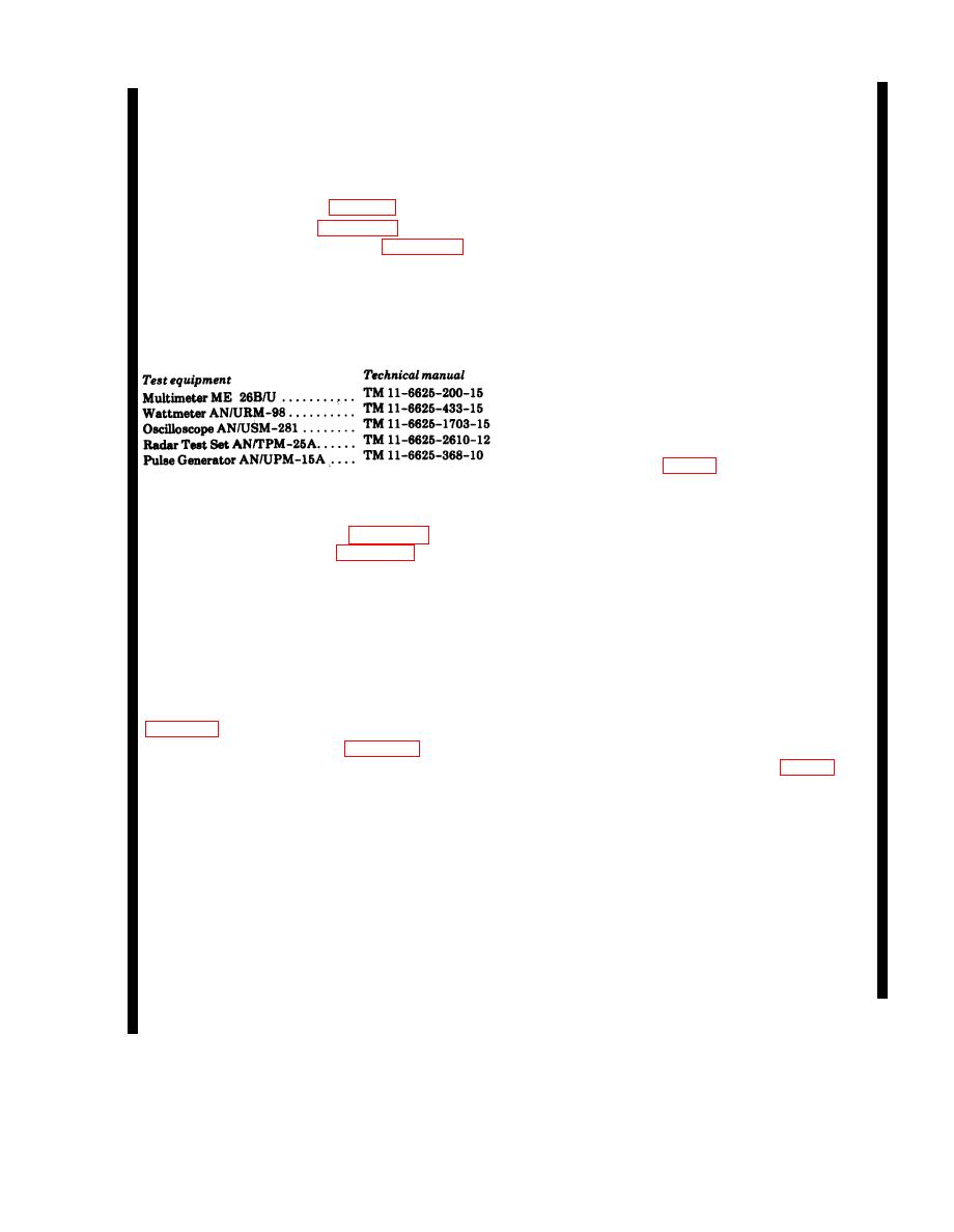
a. Standard Test Equipment. The following
(13) Connect the dc probe to test point
chart lists the Army test equipment required for
A16TP3. Adjust variable capacitors A16C17 and
the tests.
A16C18 for a maximum peaked meter indication.
The voltage should be less than 16 volts dc.
d. Final Power Level Adjustments.
(1) Turn on the equipment, and permit a 15-
minute warmup. Connect test point A13TP2
(ground to A4TP5 (fig. 3-6).
(2) Set the test set FUNCTION control at
b. Test Setup. Instructions for the applicable
SYSTEM, MODE switch at 1, and ISLS switch
test setup are provided in c and d below. Test
at OFF:
point location is shown in figure 3-6 and ad-
(3) Set the summation Bridge TS-779A/U
justment control location in figure 3-7.
RANGE switch at 0 DBM.
c. Premliminary Procedure. The preliminary
Probe
Waveguide
( 4 ) Disconnect
procedure is given in (1) through (13) below. The
M X - 2 1 4 4 A / U from the AN/APM-123(V)l
final adjustment is in d below.
PROBE connection. Adjust the TS-779A/U
NOTE
meter to zero with the ZERO control.
Wattmeter AN/URM-98 should be
(5) Reconnect the MX-2144A/U to the
warmed up for 15 minutes before final
AN/APM-123(V)l PROBE connection. Observe
adjustments are made.
the meter indication. The power should be 6 1
dBm.
(1) Remove the transmitter from its case
NOTE
I f necessary, adjust the test set
(2) Use the test setup in figure 3-1.
A16A1C2 and power controls (fig. 3-7)
(3) Set the ME-26/U SELECTOR switch
at (+) and RANGE switch at 800V.
to obtain performance standards.
(4) Apply power to the test set, and set the
(6) Disconnect test point A13TP2 (ground
test set PRESS TO TEST switch at LOCK and
from A4TP5, and connect it to test point A4TP4.
MODE switch at 1.
(7) Disconnect the MX-2144A/U from the
(5) Connect dc probe to A14TP3.
AN/APM-123(V)l PROBE connection. Set the
(6) Adjust A14R8 until meter indicates
TS-779A/U RANGE switch to -10 DBM and
+150 2 volts.
again zero its meter with the ZERO control.
(7) Disconnet the dc probe from test point
(8) Reconnect the MX-2144A/U to the
A14TP3, and set the ME-26B/U RANGE switch
AN/APM-123(V)l PROBE connection. Observe
at 30V.
the TS-779A/U power meter indication. It should
(8) Connect the dc probe to test point
just barely move upscale (approximately 21
A16TP4. Adjust control A16A2R1 for +180.5
dB).
volts.
(9) Disconnect the dc probe from A16TP4
Change 5 4-7
|
|
Privacy Statement - Press Release - Copyright Information. - Contact Us |
