 |
|||
|
|
|||
|
Page Title:
Transmitter Power and Pulse Adjustments |
|
||
| ||||||||||
|
|
 TM 11-6425-667-45/NAVAIR 16-30APM123-2/ TO 33A1-3-367-22
NOTE
NOTE
If necessary, adjust control A4R41 to
If necessary, adjust control A16R6.
obtain performance standards for the
f i r s t and last pulse. Adjust control
AN/APM-270 and the AN/USM-281A. Make
A4R29 to obtain performance standards
the connections shown in B, figure 3-4. Set and
for the second pulse.
adjust the controls as follows:
(1) Apply power to the equipment and
(7) Adjust the oscilloscope TIME BASE A
permit it to warm up for 5 minutes.
a n d B TIME/CM controls to observe two
groups of interrogation pulses. Measure the
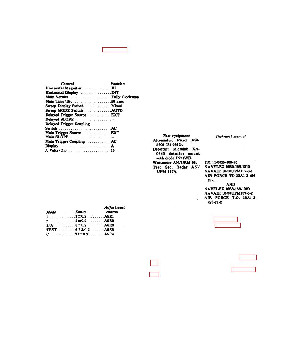
(2) Set and adjust the oscilloscope controls
as given in the chart below:
spacing between the first pulse of each group. It
should be between 4,255 and 4,545 micro-
seconds (equal to prf of 2305, -10pps).
NOTE
If necessary, adjust control A5R31 to
obtain performance standards.
4-4.1. Transmitter Power and Pulse Adjust-
ments Using AN/UPM-137A
a. Test Equipment Required. The following
chart lists the test equipment required.
(3) Set the test set FUNCTION switch at
SYSTEM and ISLS switch at OFF.
(4) Set the test set to each mode in the
following chart. Use the oscilloscope to observe
the spacing between the first and last pulse.
P e r f o r m a n c e standards are listed with the
c o n t r o l s to be used if an adjustment is
necessary.
b. Test Setup. Instructions for the applicable
test setup are provided in c and e below. Test
point location is shown in figure 3-6 and ad-
justment control location in figure 3-7.
c. Preliminary Procedure. The preliminary
procedure is given in (1) through (6) below. The
final power level adjustment procedure is given
NOTE
in d and the transmitter pulse adjustment
Control A5R6 should be adjusted for a
procedure is given in e .
symetrical P3 pulse shape.
(1) Remove test set from its case (para 3-
(5) Set the test set ISLS switch to ON.
Measure the spacing between the first and
(2) Perform procedure given in paragraph
second pulse. It should be 20.1 microseconds.
NOTE
( 3 ) Connect dc test probe to test set
If necessary, adjust control A4R22 to
AJ6TP4. Adjust control A16A2R1 for
obtain performance standards.
+ 1 8 0 . 5 vdc.
(6) Measure the width of each pulse. The
( 4 ) Connect dc test probe to test set
width should be 0.80.l microsecond.
Change 4 4-3
|
|
Privacy Statement - Press Release - Copyright Information. - Contact Us |
