 |
|||
|
|
|||
|
Page Title:
Transmitter Power and Pulse Adjustments |
|
||
| ||||||||||
|
|
 TM 11-6625-667-45/NAVAIR 16-30APM123-2 TO 33A1-3-367-22
A16TPl. Adjust variable capacitor A 16C6 for
maximum negative voltage.. Voltage should be
--20 vdc minimum.
( 5 ) Connect dc test probe to test set
A16TP2. Adjust variable capacitor A16C12 for
a maximum negative voltage. Voltage should
be -20 vdc minimum.
( 6 ) Connect dc test probe to test set
(3) Set the test set FUNCTION switch at
A16TP3. Adjust variable capacitors A16C17
SYSTEM and ISLS switch at OFF.
and A16C18 for maximum voltage. Voltage
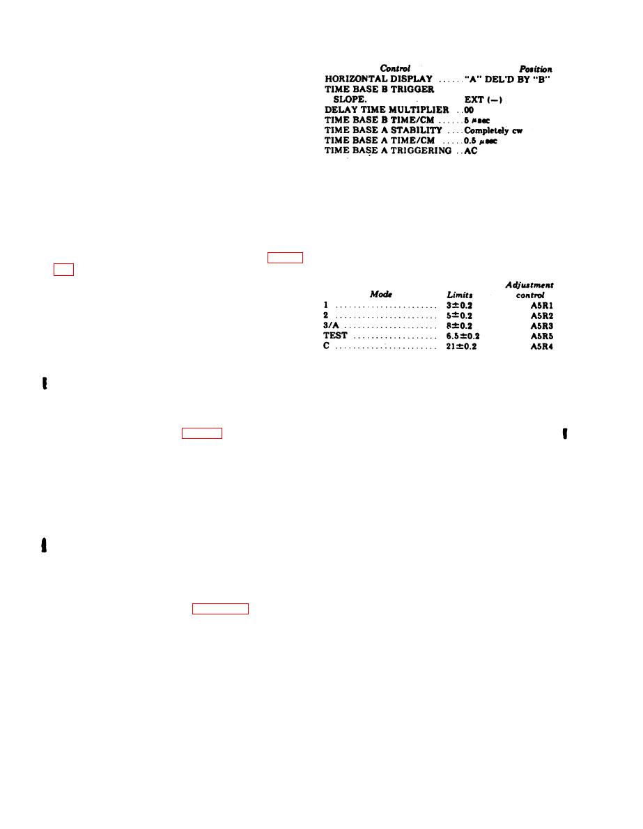
(4) Set the test set to each mode in the
should be +6 vdc minimum.
following chart. Use the oscilloscope DELAY
d. Final Power Level Adjustments.
TIME MULTIPLIER control, and measure the
(1) Connect test set A13TP2 (ground) to
s p a c i n g between the first and last pulse.
A4TP5.
(2) Set test set ISLS switch to OFF.
P e r f o r m a n c e standards are listed with the
controls to be used if an adjustment is
(3) Connect equipment as shown in figure
necessary.
( 4 ) Set Summation Bridge TS-779A/U
( p a r t of wattmeter AN/URM-98) RANGE
switch to -- 5 DBM.
(5) Disconnect cable from test set PROBE
jack and adjust Summation Bridge TS-779A/U
ZERO control to zero meter.
(6) Reconnect cable to test set PROBE
jack. Observe meter indication. Power should
NOTE
Control A5R6 should be adjusted for
be-9 1 dbm.
symmetrical P3 pulse shape.
NOTE
(5) Set the test set ISLS switch to ON.
I f necessary, adjust test set control
M e a s u r e the spacing between the first and
A16A1C2 and power controls A16A1C2
second pulse. It should be 2 0.1 s e c .
and power controls (fig. 3-7) to obtain
performance standard.
NOTE
(7) Disconnect test set A13TP2 (ground)
If necessary, adjust control A4R22 to
from A4TP5 and connect to A4TP4.
obtain performance standards.
( 8 ) Set Summation Bridge TS-779A/U
(6) Measure the width of each. pulse. The
RANGE switch to 10 DBM.
width should be 0.8 0.1 microsecond.
(9) Repeat step (5).
NOTE
(10) Reconnect cable to test set PROBE
If necessary, adjust control A4R41 to
obtain performances standards for the
jack. Observe meter indication. Power should
be -21 1 dbm.
f i r s t and last pulse. Adjust control
NOTE
A4 R29 to obtain performance standards
for the second pulse.
If necessary, adjust test set control
(7) Adjust the oscilloscope TIME BASE A
A16R6 to obtain performance standard.
a n d B TIME/CM controls to observe two
e. Transmitter Pulse Adjustments. Connect
groups of interrogation pulses. Measure the
the equipment as shown in figure 3-4B. Set and
spacing between 4,255 and 4,545 microseconds
adjust the controls as follows:
(equal to prf of 230 5 --10 pps).
(1) Apply power to equipment and permit
5-minute warmup.
NOTE
(2) Set and adjust the oscilloscope controls
If necessary, adjust control A5R31 to
as given in the chart below.
obtain performance standards.
4-4
Change 4
|
|
Privacy Statement - Press Release - Copyright Information. - Contact Us |
