 |
|||
|
|
|||
|
Page Title:
Receiver Section and Decoder Section Adjustments Using AN/TPM-26A |
|
||
| ||||||||||
|
|
 TM 11-6625-467-45/NAVAIR 16-30APM123-2/TO 33A1-3-367-22
NOTE
NOTE
If necessary, adjust control A16R6.
If necessary, adjust control A4R1 to
obtain performance standards for the
first and last pubs. Adjust control
AN/TPM-25A and the AN/USM-281A. Make
A4R29 to obtain performance stan-
the connections shown in figure 3-24. Set and
dards for the second pulse.
adjust the controls as follows:
(1) Apply power to the equipment and permit
(7) Adjust the oscilloscope MAIN AND
it to warm up for 5 minutes.
DELAYED TIME/DIV controls to observe two
(2) Set and adjust the oscilloscope controls
groups of interrogation pulses. Measure the
as given in the chart below:
spacing between the first pulse of each group. It
should be between 4,255 and 4,545 microsecond
Control
Position
(equal to prf of 230 5, -10) pps.
HORIZONTAL MAGNIFIER
XI
NOTE
HORIZONTAL DISPLAY
INT
If necessary, adjust control A5R31 to
MAIN VERNIER
Fully
obtain performance standards.
Clockwise
50 SEC
MAIN TIME/DIV
4-8. Receiver Section and Decoder Section
SWEEP MODE Switch
AUTO
INT AUTO/EXT/EXT 10
EXT
Adjustments Using AN/TPM-26A
- SLOPE +
a. Test Equipment. The test equipment lists
AC
DELAYED ACS/ACF/AC/DC
in the chart below is required for these ad
MAIN EXT+10/EXT/INT/LINE
EXT
MAIN - SLOPE +
justments.
MAIN ACS/AFC/AC/DC
AC
Test equipment
Technical manual
DISPLAY
ALT
Test Set, Radar AN/TPM-25A . . . . . . TM 11-6625-2610-1
A VOLTS/DIV
10
Multimeter ME 26B/U . . . . . . . . . . . . TM 11-6625-200-15
(3) Set the test set FUNCTION switch at
Oscilloscope AN/USM-281A. . . . . . . . TM 11-6625-1703-15
SYSTEM and ISLS switch at OFF.
Generator, Pulse AN/USM-15A.. . . . TM 11-6626-368-10
b. System Timing Setup. P e r f o r m t h e
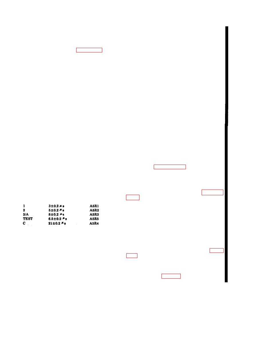
(4) Set the test set to each mode in the
procedures in paragraph 3-15d step 4 a through
following chart. Use the oscilloscope to observe
d. Once set, do not change AN/UPM-15A
the spacing between the first and last pulse.
DELAY setting.
Measure spacing from leading edge to leading
c. Test Setup.
edge. Performance standards are listed with the
controls to be used if an adjustment is necessary.
(1) Perform the s y s t e m timing setup
specified in step 4 of the chart in paragraph
Adjustment
control
Mode
Limits
(2) On the A N / T P M - 2 5 A adjust SUM
ATTEN for a reading of -9 dB less the 1090
MHz loss of cable 139526. This establishes the
test conditions for all receiver and decoder ad
justments.
NOTE
NOTE
Control A5R6 should be adjusted for a
Disregard the specified measurements
symmetrical P3 pulse shape.
and the normal indication columns in
the chart.
(5) Set the test set ISLS switch to ON.
(3) The ME-26B/U is not shown in figure
Measure the spacing between the first and second
pulse. It should be 3 0.1 s.
are provided in f below for its connections and
NOTE
use.
If necessary adjust control A4R22 to
d. Receiver Sensitivity Adjustment. Adjust
obtain performance standards.
control A8R5 (fig. 3-7) completely coun-
(6) Measure the width of each pulse. The
terclockwise. Then, turn the control until the
width should be 0.8 0. 1 s.
4-8
Change 5
|
|
Privacy Statement - Press Release - Copyright Information. - Contact Us |
