 |
|||
|
|
|||
|
Page Title:
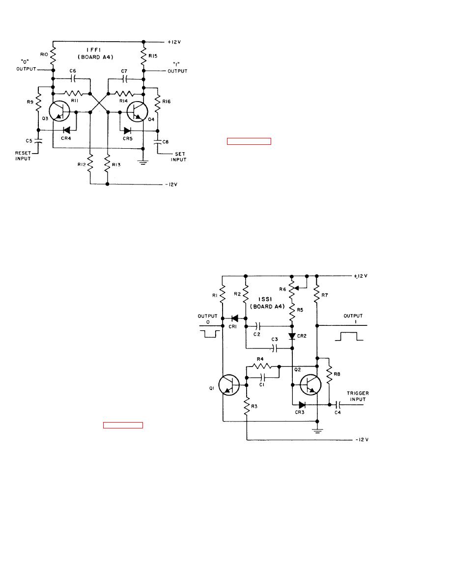
Figure 28. Typical one-shot circuit. |
|
||
| ||||||||||
|
|
 TM 11-6625-667-45/NAVSHIPS 0969-249-8010/NAVAIR 16-30APM123-22/TO 33A1-3-367-22
C4 drives normally conducting Q2 to cutoff. Its
rising collector potential is coupled by R4 to the
base of Q1, driving Q1 into conduction. Capacitor
C2 then starts discharging. and when discharged.
the base of Q2 is driven positive. The one-shot then
returns to its original state.
c. Gates. OR gates used in the test set are the
simple diode types and are not described. Various
types of AND gates exist and there are several
ways of using them; those used in the test set are
described in (1) and (2) below.
( 1 ) Figure 2-9 illustrates a typical diode
AND gate CR1 and CR2 with the inputs con-
nnected to a typical signal source. This circuit is
presented for analysis and does not represent any
specific one in the test set. Two positive signals
must be present at the input of the diodes fit the
same time to cause an AND gate output. The nega-
tive signal at Q2 stops conducting and its collector
TYPICAL
FLIP-
FLOP
CIRCUIT
potential goes positive. This aiction blocks the cur-
TM6625-667-35-9
rent flow through CR2 and provides an enabling
Figure 2-7. Typical flip-flop multivibrator circuit.
voltage at gate diode CR2. When the negative
pulse appears at the input of Q1, its conduction is
stopped. The AND gate is thus enabled by Q2
cut off by the input, and in turn drives Q3 into
conduction. This is the set state, with Q3 provid-
ing the low 0 output and Q4 a high 1 output.
Resistors R9 and R16 bold the respective inputs
high when their stages are not, conducting, to pre-
vent any additional pulses at the high input from
switching a flip-flop state. Thus, an input to the
conducting stage only will change the state. Flip-
flops that have trigger inputs will assume the op-
posite state with an active signal at the input, of
the concluding stage. The signal is coupled to
both stages to force the change in state.
b. One-Shots. All one-shots in the test set are
similarlv constructed. Some one-shots are trig-
gered from the leading edge. of the input pulse and
some are triggered from the trailing edge. The
major difference, between one-shots is the rc time
constant. that determines the duration of the out-
put. Each one-shot has a control to adjust the
width of its output pulse. Figure 28 illustrates a
typical one-shot circuit. In this circuit, an output,
is taken from each stage. In some circuits, only one
of tile outputs shown is used. The time constant of
TYPICAL
SINGLE-
SHOT
CIRCUIT
TM6625-667-35-10
the one-shot shown is determined by capacitor C2,
resistor R5, and control R6. A trigger applied to
Figure 28. Typical one-shot circuit.
2-14
Change 4
|
|
Privacy Statement - Press Release - Copyright Information. - Contact Us |
