 |
|||
|
|
|||
|
|
|||
| ||||||||||
|
|
 TM 11-6625-549-14-1
changed periodically by the TM 11-6625-542-14-1 trigger
5-12.
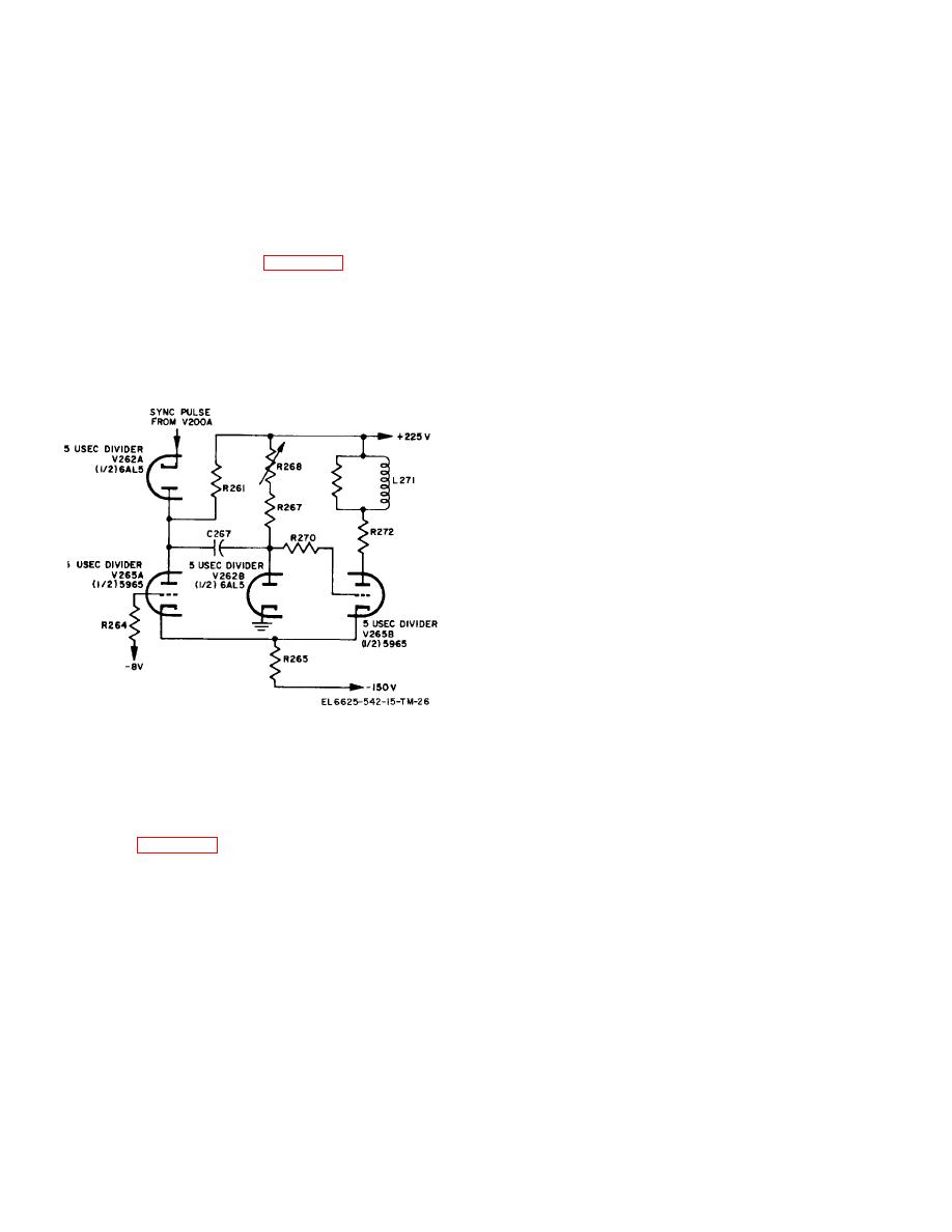
50 MC Multiplier
pulses from V200A. The cycle starts in this example with
This multiplier is composed of 50 megacycle amplifier
tube V265B at zero bias and V265A at cutoff. Tube
V244 and its associated circuit components, and
V265B is held in conduction by the gridclamping action of
operates the same way as the 5 and 10 megacycle
diode V262B, while V265A does not conduct because of
multipliers. The plate tank circuit of this multiplier is
the fixed grid bias of -8 volts.
tuned to 50 megacycles and is link-coupled to the 50 MC
b. The trigger pulse which shifts the multivibrator
sine wave output switch. Plate voltage for V244 is
from a quiescent to an unstable state is a negative-going
applied only when the 50 MC pushbutton is actuated.
pulse of approximately 50 volts fed to the cathode of
5-13.
Divider Circuits
V262A. This pulse drives the cathode more negative
a. There are 13 divider circuits, each containing a
than the plate causing V262A to conduct. The plate of
triggered multivibrator circuit (figs. 5-3 and 5-4). The
V262A is coupled to the grid ofV265B through C267;
fourteenth marker receives its signal directly from the
therefore the negative pulse breaks the clamping action
crystal-controlled oscillator. The 10, 50, 100and 500
of V262B and drives the grid of V265B negative. This, in
microsecond markers are the high-frequency dividers.
turn, causes the cathode current to decrease. The
The 1, 5, 10 and 50 millisecond markers are the
decreasing cathode current through R265 causes the
intermediate dividers. The 100 and 500 millisecond and
potential on the cathode of V265A to decrease. When
the 1 and 5 second markers are the low-frequency
the voltage on the cathode decreases to -8 volts, V265A
dividers.
conducts, causing a further drop in voltage at the plate.
This negative-going voltage, like the trigger pulse, is
coupled to the grid of V265B through C267 and aids the
negative-going trigger pulse in driving V265B to cutoff.
c. As tube V265A conducts, the plate voltage
continues to drop until it reaches the same potential as
that which is on the plate of V262A (175 volts). At this
point, the plate of V262A is more negative than the
cathode and subsequent trigger pulses cannot reach the
grid of V265B. As the charge across C267 equalizes,
the grid of V265B becomes more and more positive until
the clamping action of V262B is restored.
d. At this point, the multivibrator begins to revert
to its initial state, for as V265B begins to conduct the
voltage on the cathode of V265A raises again to cutoff
potential. The subsequent drop in current through R261
causes the plate voltage of V265A to increase. As the
plate voltage of V265A increases, C267 takes on a
charge.
The multivibrator is now restored to its
Figure 5-4. Multivibrator circuit, simplified schematic
quiescent state and, in the absence of further trigger
diagram.
pulses, would remain so. But since more trigger pulses
b. Operation of each divider circuit is essentially
do follow the initial trigger, the multivibrator continues
the same.
Each circuit consists of a bi-stable
indefinitely to shift conduction from one tube to another
multivibrator with diode coupling for triggering pulses.
as described above. The values of the components in
Operation of these circuits is described in the paragraphs
the 5 microsecond divider are selected to provide an
that follow. Figure 5-4 is a simplified schematic diagram
elapsed time of 5 microseconds for each complete cycle.
of a multivibrator circuit and should be referred to during
5-15.
Cathode Follower
the following description.
Cathode follower V200A, which couples the 5 megacycle
5-14.
Multivibrator
oscillator to the 5 microsecond divider, isolates the
a. Oscillations of the multivibrator are maintained
divider stage from the oscillator. It also prevents any
by the alternate shifting of conduction from V265A to
variations in the divider from affecting the stability of the
V265B. Once started, each tube would tend to conduct
oscillator.
indefinitely if the potential on the tube elements were not
5-3
|
|
Privacy Statement - Press Release - Copyright Information. - Contact Us |
