 |
|||
|
|
|||
|
|
|||
| ||||||||||
|
|
 TM 11-6625-3017-14
-12 V line should be not more than +2 mV,
5.4.3 Power supply
and preferably about +1 mV.
Test equipment:- a, b, c and d
5.4.4
Local oscillator
(1)
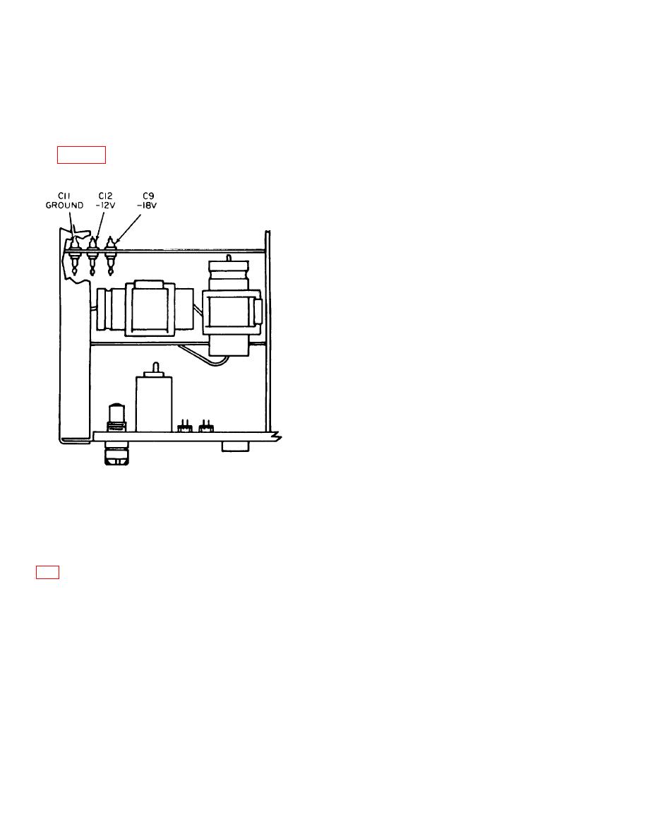
Measure the output of the -18 V and -12 V
regulated supplies at the points illustrated in
Test equipment:- e, f, g' and h
(1)
Connect the frequency meter and millivolt-meter via
a T-connector to the output plug of the oscillator,
PLB. Turn the LEVEL control fully clockwise.
(2)
Switch to oscillator RANGE 1-2, tune through the
range and check that the dial calibration is within
3% of the frequency meter reading and that the
level is between 0.5 V and 1 V. If the calibration
accuracy is outside limits, withdraw the local
oscillator unit and reset range trimmer L2 for
optimum accuracy at the low frequency end and/or
C1 at the high frequency end. Replace the local
oscillator unit and recheck the calibration.
(3)
Switch to oscillator RANGE 3-4, tune through the
range and check that the dial calibration is within
+3% of the frequency meter reading and that the
level is between 0.6 V and 0.8 V. If the calibration
accuracy is outside limits withdraw the local
oscillator unit and reset range trimmer LA for
optimum accuracy at the low frequency end and/or
C14 at the high frequency end. Replace the local
oscillator unit and recheck the calibration.
(4)
Switch to oscillator RANGE 3-4 and turn the
CRYSTAL switch to position 1. Insert a 22 MHz
Fig. 5-2. Regulated supply measuring paints
crystal into socket 1 and check that the frequency
meter reads within 22 MHz the crystal tolerance
If the voltages are not within 1% of nominal, adjust
after tuning the Local Oscillator to 22 MHz.
RV1 for -18 V or RV2 for -12 V.
5.4.5
The location of these potentiometers is illustrated in Fig.
Test equipment:- i.
(1)
Shunt the resistor in series with the I. F. OUT
(2)
Connect the wave analyser to the -18 V line and
socket by a 1 k2 resistor.
check that the 50 Hz, 120 Hz and i80 Hz ripple
components are each less than 100 -V. Check
(2)
Connect the I. F. OUT socket to the R. F. Input of
that the same components on the -12 V line are
the Polyskop and the R. F. IN socket to the R. F.
each less than 50 - V.
Output of the Polyskop.
(3)
Replace the wave analyser with the differential
(3)
Set the Polyskop controls as follows:
voltmeter. Check that the -18 V line voltage does
not change by more than 20 mV when the a. c.
supply is varied from 180 to 260 V, (or 90 to 130 V).
The change on the
5-5
|
|
Privacy Statement - Press Release - Copyright Information. - Contact Us |
