 |
|||
|
|
|||
|
Page Title:
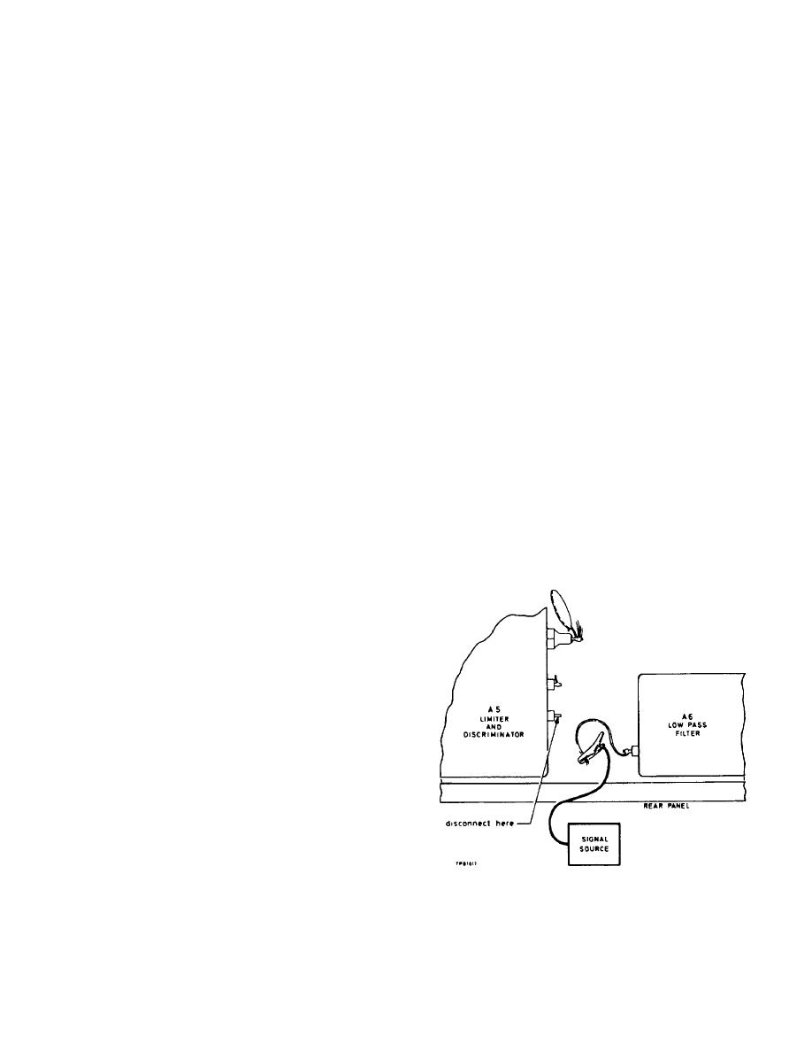
Fig. 5-3. Location of discriminator output lead. |
|
||
| ||||||||||
|
|
 TM 11-6625-3017-14
Output Attenuator:
30 or 40 dB.
frequency; the frequency blip will then be shown on the
Sweep Width control:
maximum sweep.
Polyskop. It is advisable to adjust the Polyskop
Centre Frequency
frequency control and the OSCILLATOR TUNE control
control:
mid-way.
together, so that the correct frequency blip remains on
Y1 Gain control:
maximum gain.
the screen.
Y1 switch:
B.
Y2 switch:
off.
(7)
If the sensitivity at any min is below that specified,
adjust capacitor A2bC7 and the position of the
Set the TF 2300 controls as follows:
tuning slug in coil A2bL2 to increase the amplitude
where the frequency blip is a minimum. It may also
SUPPLY:
on.
be necessary to select a new value for A2bC14.
Oscillator RANGE:
RANGE 5 - 8.
CRYSTAL:
OFF
NOTE:
Capacitors C7 and C14 will need to be set
(4)
Adjust the OSCILLATOR TUNE control to about 88
to a compromise position to give the best sensitivity
MHz on the tuning scale, i. e. A local oscillator
throughout the frequency range, as there will be more
frequency of 22 MHz.
than one minimum sensitivity point. Sensitivity becomes
approximately correct if the input attenuator on the
(5)
Set the Frequency switch on the Polyskop to about
Polyskop can be set to the 30 or 40 dB position. While
50-100 MHz and the Frequency Markers switch to
the checks are being carried out, note that no spurious
50 MHz.
oscillations occur.
The Polyskop screen will show a sweep between 50
and 100 MHz with the 50 MHz marker pips at each
5.4.6
De-emphasis
end of the trace.
Test equipment: j and k
The 88 MHz signal, i. e. 4th harmonic of the 22 MHz
from local oscillator, will show as a double blip at 88
(1)
With the modulation meter switched off, disconnect
MHz on the trace. Tune the local oscillator over the
the yellow lead from the discriminator unit output
frequency band, i. e. increase frequency and the
(A5, pin 4) and connect the lead to the output of the
frequency blip on the Polyskop should move
signal source.
towards the 100 MHz marker.
Range 5 on the TF 2300A covers 88-176 MHz;
therefore, when the 100 MHz blip reaches the 100
MHz marker, change the Frequency switch on the
Polyskop to 100-200 MHz and the 100 MHz blip will
appear superimposed on the 100 MHz marker at
the beginning of the trace. Continue to tune through
the range to 176 MHz:
(6)
Then tune the local oscillator through the remaining
frequency ranges up to 1000 MHz and note the
frequencies at which the frequency blip shown on
the Polyskop is a minimum and measure the
sensitivity at these points using the signal generator
and the R. F. millivoltmeter.
NOTE:
When using the Polyskop above 400 MHz,
the variable frequency control must be set to the required
frequency and the OSCILLATOR TUNE control on the
TF 2300 should be tuned to this
Fig. 5-3. Location of discriminator output lead.
5-6
|
|
Privacy Statement - Press Release - Copyright Information. - Contact Us |
