 |
|||
|
|
|||
|
|
|||
| ||||||||||
|
|
 TM 11-6625-3017-14
2nd harmonic: (fl -f2):
2 kHz
3rd harmonic: (2f2 -fl):
12 kHz
and express them in dB's relative to 0 dB. Add +6 dB to
the 2nd harmonic reading and +9 dB to the 3rd harmonic
reading. The r. m. s. sum of the two levels (see below
for method of calculation) should be lower than -54 dB
(0. 2%. Distortion limits for other values of deviation and
Fig. 4-7. A.M. rejection measurement
modulation frequency are given in Sect. 1.2 - Data
Summary.
(3) Switch to F. M. - SET FREQ and adjust the
OSCILLATOR tune control to bring the meter reading to
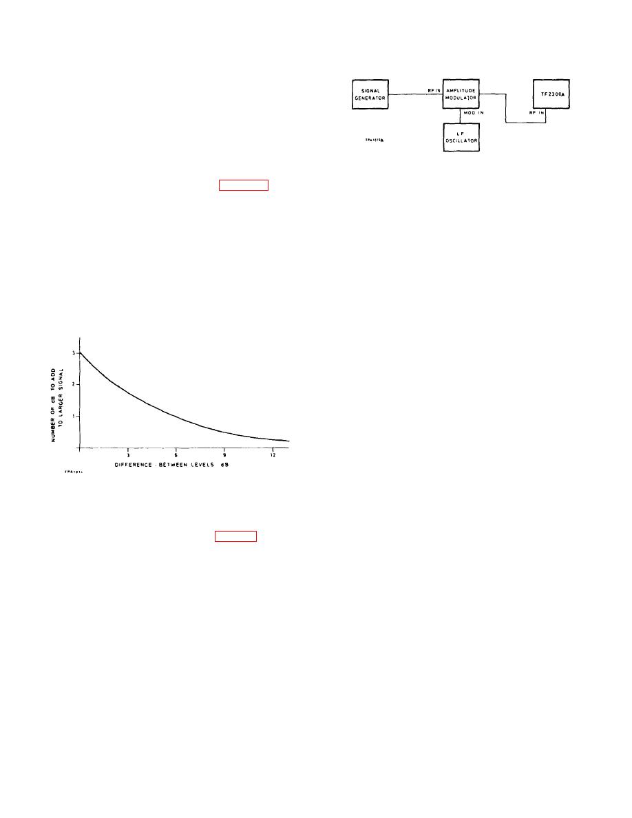
Summation of dB levels
the SET mark.
The r. m. s. sum of two dB levels can be obtained
(4)
Switch to TUNE and adjust the LEVEL control to
by increasing the level of the larger one by an increment
give a reading just below full-scale on the
between 0 and 3 dB; the value of increment depends on
black arc.
the difference between the two levels as shown by the
graph. For example, if the two levels are -40 dB and -46
(5)
Turn the DEV RANGE switch to 5 kHz and the MAX
dB, giving a difference of 6 dB, the increment is 1 dB; the
MOD FREQ switch to 15 kHz.
sum of the two levels is therefore -40 +1 dB = -39 dB.
(6)
Switch to DEV+ and DEV- in turn and check that
the residual reading on the meter is less than about
Fig. 4-6. Summation of dB levels
150 Hz.
4.4 CLEANING AND LUBRICATING
Rotary switch contacts
These should be cleaned once or twice a year,
depending on usage, with benzine or white spirit (not
carbon tetrachloride). After cleaning wipe the contacts
with a suitable lubricant such as a 1% solution of
petroleum jelly in white spirit.
4.3.7
A.M. rejection
Oscillator unit
Test equipment:- a, f and m.
Excessive lubrication must be avoided but the
moving parts should be cleaned and lubricated at least
(1) Set up the equipment as shown in Fig. 4-7. Adjust
twice a year:
the signal generator to give a c. w. output of 100 mV at
any convenient frequency. Adjust the I. f. oscillator
(a)
Worm shaft: Use Rocol anti-scuffing paste.
frequency to 1 kHz at a level which gives 80%
modulation as measured on the TF 2300A.
(b)
Carriage slide: Use Aeroshell 4 oil.
(2) On the TF 2300A set the Function switch to TUNE
(c)
Scale drum mounting: Apply a few drops of
and the OSCILLATOR TUNE control to give maximum
Aeroshell 4 oil to the felt washer on the spigot
meter reading. Then adjust the LEVEL control for a
mounting.
reading within the black arc.
(d)
Range switch bevel gears: Use Rocol anti-
scuffing paste.
Note:
Sealed bearings at end of worm shaft will not
require lubrication within the life of the instrument.
4-8
|
|
Privacy Statement - Press Release - Copyright Information. - Contact Us |
