 |
|||
|
|
|||
|
Page Title:
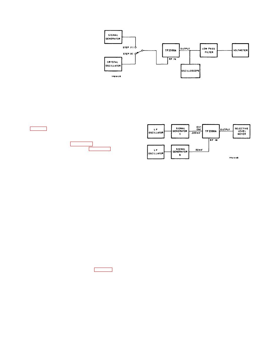
Fig. 4-5. F.M. distortion measurement |
|
||
| ||||||||||
|
|
 TM 11-6625-3017-14
Fig. 4-4. F.M. noise
measurement
To ensure that the latter output is due to the modulation
meter alone it is important that the source should be
(2)
On the modulation meter set the Function switch to
exceptionally free from spurious noise deviation.
TUNE and the oscillator RANGE switch to EXT.
Adjust the frequency of c for maximum reading on
the TF 2300A meter and adjust the TF 2300A
(1)
Apply an f.m. input with 5 kHz deviation from the
LEVEL control for a reading within the black arc.
signal generator. Connect the oscilloscope, filter
and voltmeter to the OUTPUT terminals as shown
in Fig. 4-4.
(2)
Set
the
modulation
meter
for
deviation
measurement as in Sect. 2.5, with the local
oscillator crystal-controlled (see Sect. 2.15). Switch
the DEV RANGE to 5 kc/s and the MAX MOD
FREQ to 15 kHz.
Fig. 4-5. F.M. distortion measurement
(3)
Note the reading on the voltmeter - this should be
about 0 dBm if the modulation meter is terminated
(3)
Switch to F. M. SET FREQ and adjust c frequency
in 600 n.
to bring the TF 2300A meter reading to the SET
mark.
(4)
Replace the signal generator with the external
crystal oscillator set to the same output level and
(4)
Switch to DEV+ and turn the MAX MOD FREQ
note the reduction in volt-meter reading. This
switch to 15 kHz and the DEV RANGE switch to
should be at least 50 dB, which is equivalent to a
150 kHz.
noise level of -70 dB with reference to 50 kHz
deviation in a 15 kHz bandwidth.
Apply external modulation to the two signal generators
as follows:
(5)
Note that the oscilloscope trace is free from hum,
external field and noise. If not, check the power
TABLE 4.4
supply ripple - see Sect. 5.4.3.
External Modulation
Sig. gen.
Mod. freq.
Deviation
4.3.6
F.M. distortion
c
16 kHz (fl)
37.5 kHz
Test equipment:- b, c, 2f and i.
b
14 kHz (f2)
37.5 kHz
(1)
Set up the equipment as shown in Fig. 4-5. Adjust
c to give a c. w. output of 200 mV at any convenient
Switch off b and set up the level meter to give a
frequency Fc1. Adjust b to give a c. w. output of 50
reference level of -6 dB at 150 kHz. Switch on b again.
mV at frequency (Fc1- 1.5 MHz).
Measure the levels of the following components: -
4-7
|
|
Privacy Statement - Press Release - Copyright Information. - Contact Us |
