 |
|||
|
|
|||
|
|
|||
| ||||||||||
|
|
 TM 11-6625-3017-14
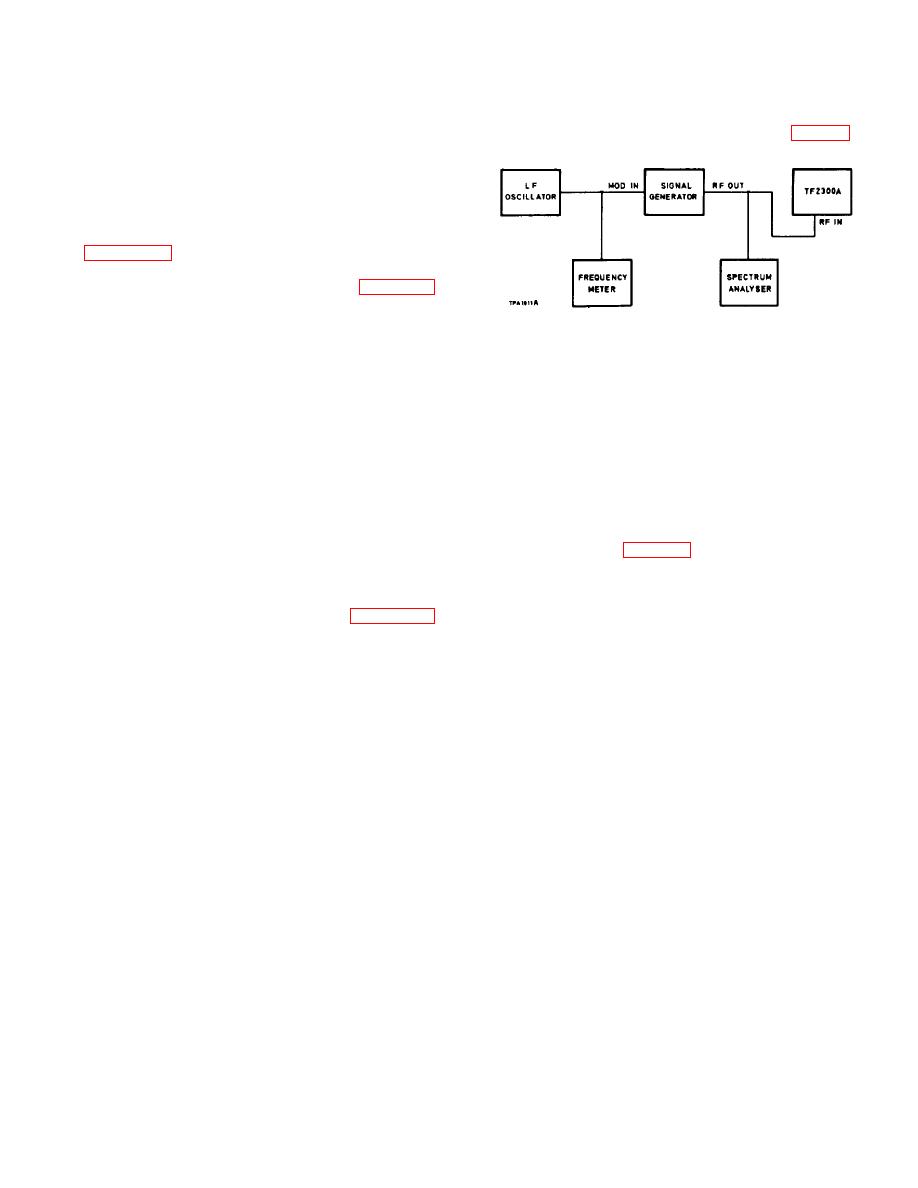
(1) Connect the signal generator, externally modulated
I.F. output and frequency
by the l. f. oscillator, to the inputs of the modulation
meter and the spectrum analyser, as shown in Fig. 4-3.
(6)
Connect the frequency meter and voltmeter to the
I.F.
OUT socket and check that the i.f. is
approx.200 mV (with the meter reading at the
bottom ofthe black arc) and remains within 10% of
1.5 MHz when the modulation depth of the input
signal is varied from 0 to 80%o. (Keep the leads as
short at possible.) If the frequency is in error see
NOTE
: Follow steps (4), (5), and (6) of section 2.5
to set the Function switch to F.M. SET
FREQ. and tune the oscillator frequency to
position the meter pointer to the SET line.
Fig. 4-3. Bessel zero measurement
I.F. output impedance
(2)
Adjust the oscillator frequency, checked against the
frequency meter, to 26.27 kHz. Slowly increase the
(7)
Adjust the LEVEL control to increase the voltage at
signal generator deviation from zero until the carrier
the I.F. OUT socket to 700 mV. Connect a 10 k Ω
component, viewed on the spectrum analyser,
2% resistor across the voltmeter input and check
disappears for the second time. This occurs at a
that reading drops to between 310 and 400 mV.
deviation ratio of 5.52, which means that the
deviation is 145 kHz.
(The MAX MOD
FREQUENCY should be 200 kHz.)
4.3.3 F.M. deviation accuracy
(3)
Set up the modulation meter to measure this signal
Test equipment:- b, d, e and g.
as described in Sect. 2.5, using the 150 kHz DEV
RANGE.
The internal f. m. calibrator provides a standard of
good long-term stability for checking and resetting the
(4)
If the modulation meter reading differs from 145
deviation reading accuracy as described in Section 2.5
kHz when switched to either DEV+ or DEV-, adjust
(8). The calibrator accuracy is largely dependent on the
the SET CAL F. M. preset to give the best
frequency of its 200 kHz oscillator crystal, which is
compromise
accuracy
between
the
two
unlikely to change significantly. If the calibrator accuracy
measurements. Then turn the
is suspected, the deviation reading should be checked by
making a normal measurement on a symmetrically
modulated signal of accurately known deviation set up by
the Bessel Zero method described below.
TABLE 4.2
F.M. Deviation Accuracy
DEV RANGE
MAX MOD
Deviation
Modulating
Carrier
kHz
FREQ range
kHz
frequency
disappearance
kHz
kHz
500
200
480
55.46
3
200
360.7
150
1
200
145
26.27
2
150
200
145
26.27
2
15
48
8.696
2
50
15
48
8.696
2
15
14.5
2.627
2
15
14.5
2.627
2
15
4.8
0.8696
2
5
15
4.8
0.8696
2
1.5
15
1.4
0.5822
1
4-5
|
|
Privacy Statement - Press Release - Copyright Information. - Contact Us |
