 |
|||
|
|
|||
|
Page Title:
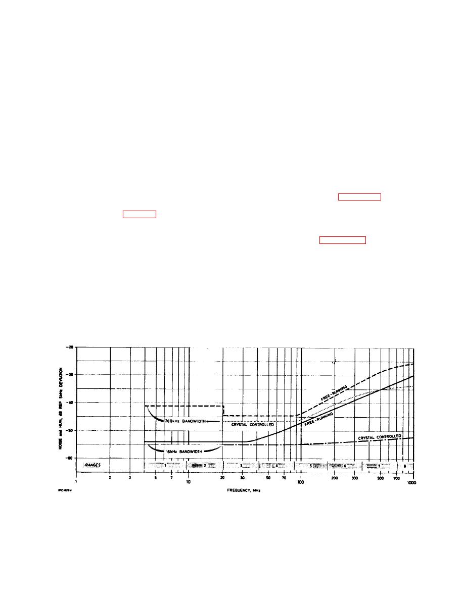
Fig. 2-4. Typical modulation meter noise levels |
|
||
| ||||||||||
|
|
 TM 11-6625-3017-14
For noise measurements in other bandwidths
width in which the measurement is to be made
select the MAX MOD FREQUENCY 200 kHz band- width
and the carrier frequency.
setting and use a similar type of low-pass filter designed
for the required cut-off frequency.
In the 200 kHz bandwidth, there is little advantage in
using crystal control below 500 MHz.
In both
(2)
The output of the modulation meter is 0. 775 V
bandwidths, crystal control will eliminate oscillator
into 600 n for full-scale deflection on the internal
microphony and therefore may be advantageous in
meter.
conditions of vibration or high acoustic noise levels.
(3)
For measurements in the r. f. range 22 MHz to
F.M. noise
1000 MHz the local oscillator must be crystal
controlled if lowest possible internally generated
(1)
Connect an external meter to the OUTPUT
noise is required. Thus, a crystal suitable for the
terminals. Apply r. f. input at a suitable level.
appropriate frequency must be available. This is
not a requirement below 22 MHz, where the
(2)
Adjust the OSCILLATOR TUNE dial to a
internal noise of the oscillator is sufficiently low
frequency 1.5 MHz above the carrier and tune
to make crystal control unnecessary.
for peaking, as in section 2. 5(5). Then adjust
LEVEL to the top end of the black arc on internal
(4)
The curves given in Fig. 2-4 show typical noise
meter. Switch to 15 kHz or 200 kHz MAX MOD
levels produced by free-running and crystal
FREQUENCY setting, thus selecting the
controlled oscillators over the r.f. range of the
required low-pass filter in the modulation meter.
instrument. In the 15 kHz bandwidth, below 70
(See also Sect. 2.5 - Noise in f.m.
to 100 MHz, there is insignificant difference in
measurements. )
respective noise levels.
Above 100 MHz,
however, the noise level free-running increases
(3)
Switch to position F.M. SET FREQ and adjust
progressively with frequency, whereas under
the oscillator until meter reads SET.
crystal control the level remains nearly constant.
The necessity to use crystal control depends on
(4)
Switch to crystal control and check that the
the noise level of the equipment under test and,
meter still reads near to the SET mark - the
as shown by the curves, the band-
Fig. 2-4. Typical modulation meter noise levels
2-7
|
|
Privacy Statement - Press Release - Copyright Information. - Contact Us |
