 |
|||
|
|
|||
|
|
|||
| ||||||||||
|
|
 TM 11-6625-3017-14
TABLE 2.2
2.9 NOISE MEASUREMENTS
By connecting an external meter to the OUTPUT
Spurious deviations with increasing % a.m.
terminals, noise measurements limited only by the noise
level generated within the instrument can be made. The
1. LEVEL control set for meter reading at top end of arc.
internal meter, being peak reading, is not suitable for
measuring noise and, ideally, an r.m.s. responding meter
2. A.M. frequency = 1 kHz
should be used. However, sufficiently accurate results
are usually obtained with an average reading meter by
Spurious deviation
applying the appropriate correction factor.
A.M.
15 kHz bandwidth
200 kHz bandwidth
Typical meters which can be used are as follows:
30
75 Hz
750 Hz
(a)
R. M. S. valve voltmeter capable of measuring
to the necessary accuracy (1% deviation on any
80
150 Hz
2 kHz
range is approximately 7.75 mV). Errors due to
crest factor and zero shift can be avoided by
operating the meter at mid-scale by means of an
attenuator.
TABLE 2.3
Spurious deviations with increasing a.m. frequency
(b)
Marconi Instruments Sensitive Valve Volt- meter,
type TF 2600.
1. LEVEL control set for meter reading at top
end of arc.
2. A.M. depth = 80%.
(c)
Marconi Instruments Distortion Factor Meter,
type TF 2331.
Spurious deviation
(b)
and (c) are average reading and a correction of
A.M. freq.
15 kHz bandwidth 200 kHz bandwidth
+1 dB should be applied.
1 kHz
150 Hz
2 kHz
(1)
The modulation meter has two selectable f.m.
bandwidths and the appropriate filter must be
10 kHz
2 kHz
3 kHz
selected when making the test.
100 kHz
-
7 kHz
A capacitor should be connected across the
OUTPUT terminals - 0.
014 ~F for the 15 kHz
2.8 MEASURING A.M. ON F.M.
bandwidth, or 0. 0013 ,F for 200 kHz. These corrective
capacitors are necessary because of the design of the
The modulation meter may be used to indicate amplitude
filters (see section 3. 9).
modulation in a frequency modulated signal, provided
that the deviation is less than 100 kHz The procedure is
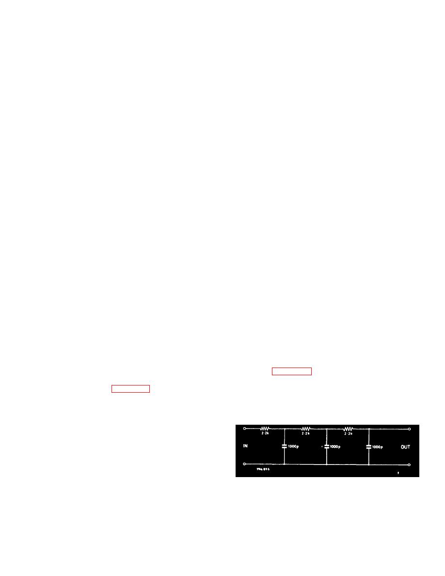
For optimum results in the 15 kHz bandwidth position
that of a.m. measurement, section 2.6.
a low-pass filter as shown below should be used
between the OUTPUT terminals and the external meter
In general, the spurious a.m. Indication will be
instead of the capacitor.
proportional to the deviation. The i. f. amplifier is set up
for optimum phase response for f.m. deviation
measurement rather than a maximally flat response for
measuring a.m. on f.m.
Below 100 kHz deviation, the internally generated
spurious a.m. is less than 2% approximately.
2-6
|
|
Privacy Statement - Press Release - Copyright Information. - Contact Us |
