 |
|||
|
|
|||
|
Page Title:
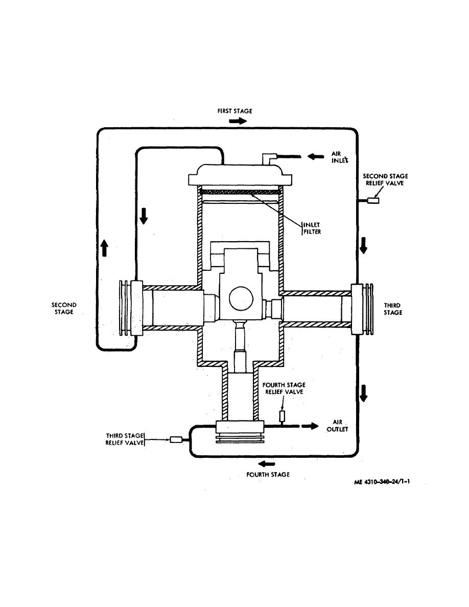
Figure 1-1. Compressed air flow-schematic. |
|
||
| ||||||||||
|
|
 TM 5-4310-340-24
components to be lubricated. A spring loaded. oil bypass.
relieved to atmosphere through the relief valves. Lubrication
relief valve is located in the crankcase permitting the oil to
of the compressor (fig 1-29 is accomplished by the gerotor
bypass from the gerotor outlet to the geroter inlet passage in
which is installed within the crankcase adjacent to the fan.
case of oil over-pressurization.
the gerotor draws filtered oil from the crankcase oil sump and
discharges
the
oil
through
the
crankshaft
to
Figure 1-1. Compressed air flow-schematic.
1-2
|
|
Privacy Statement - Press Release - Copyright Information. - Contact Us |
