 |
|||
|
|
|||
|
Page Title:
CONNECTION OF GOVERNOR TO FUEL INJECTION PUMP HOUSING (CONT) |
|
||
| ||||||||||
|
|
 3208 INDUSTRIAL AND MARINE ENGINES
DISASSEMBLY AND ASSEMBLY
FUEL INJECTION PUMP HOUSING AND GOVERNOR
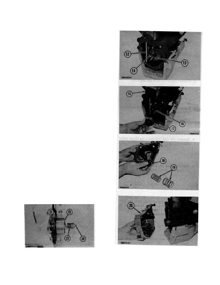
14. Put the thrust collar (13) in position be-
tween the flyweights. Lift the flyweights up
with a piece of wire and push the thrust
collar (13) forward.
15. Put the lever (14) in position in the housing
and in the groove of the thrust collar (13).
Put a new O-ring seal on the shaft and in-
stall the shaft (12) down through the hous-
ing and into the holes in lever (14).
16.
Install the cover (15) on the pump housing.
17.
Install the spring (16) on the shaft.
18.
Install the seat (17) on the shaft.
19.
Install the seat (18) and two springs (19) in
the governor housing.
CAUTION: Both springs must make a full seat on
seat (18) before installing in governor housing. If
springs do not make a full seat, high idle speed
will not be correct. Low idle governor surge can
be caused by springs not making a full seat. It
can also prevent getting a low idle setting with
stability.
20. Install the governor housing (20) on the
pump housing.
21. For fuel systems equipped with a dashpot
governor, install spring (21) on shaft (24).
Install seat and piston assembly (22) on
shaft (24). Turn spring (23) on the piston
and seat until it just contacts the shoulders
on the piston and seat.
end by:
a) make an adjustment of the fuel sys-
tem setting (See FUEL SYSTEM in
TESTING AND ADJUSTING)
b) install fuel injection pump housing
and governor
31
|
|
Privacy Statement - Press Release - Copyright Information. - Contact Us |