 |
|||
|
|
|||
|
|
|||
| ||||||||||
|
|
 FUEL SYSTEM
TESTING AND ADJUSTMENT
TIMING
INDICATOR READING
ANGLE
15
.112 in.
2.84 mm
*16
.127 in.
3.23 mm
3.63 mm
17
.143 in.
*Correct timing angle
NOTE: If the timing of the fuel system is different than
the correct timing dimension given in the chart, see the
subject CHECKING TIMING BY TIMING PIN METHOD.
Checking Automatic Timing Advance Unit By
Timing Light Method
CONSTANT BLEED VALVE
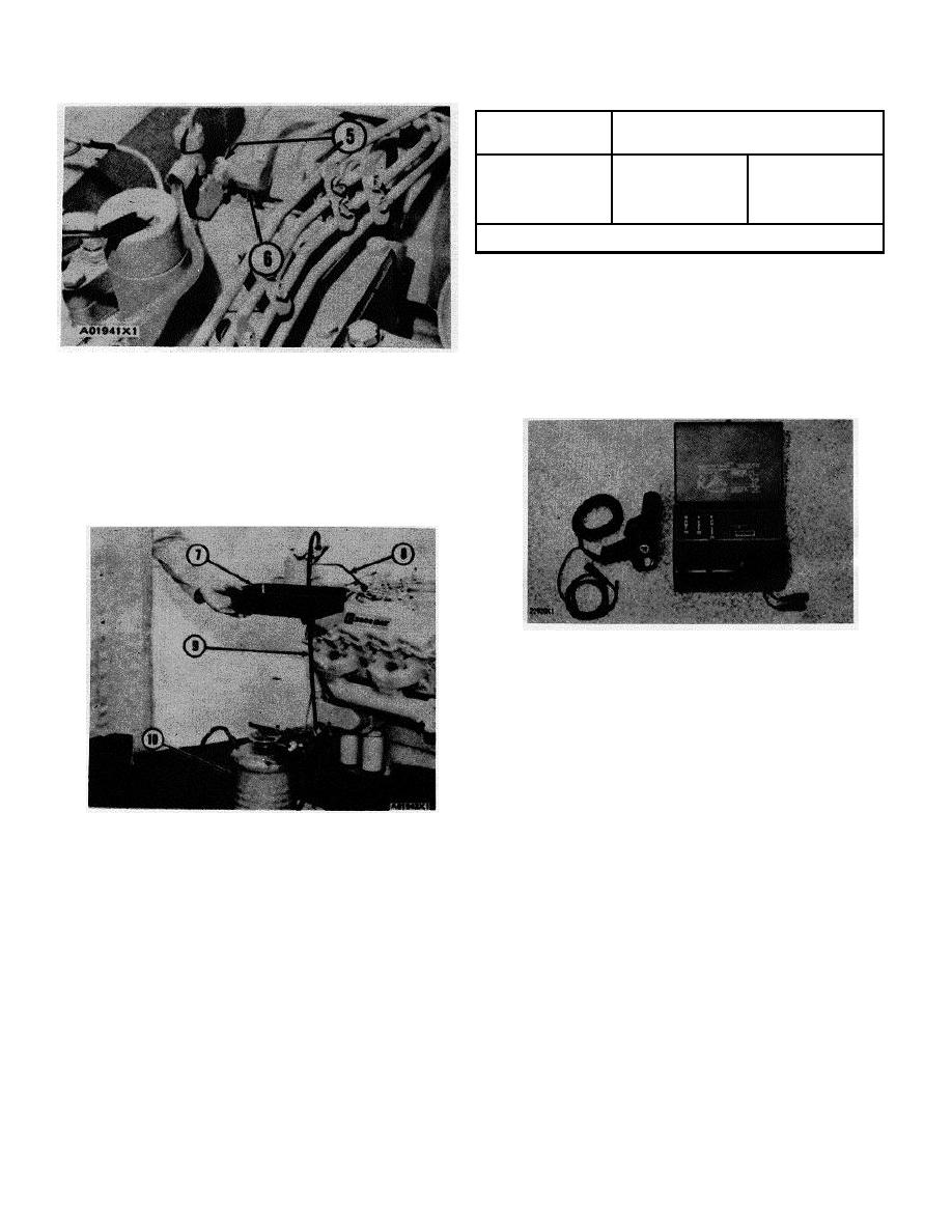
5. Constant bleed valve. 6. Cap.
Tools Needed: 1P3500 Injection Timing Group
CAUTION: If shop air is used, be sure to adjust the
2
regulator so there is no more than 15 psi (1.1 kg/cm ) of air
pressure in the tank.
13. Put pan (7) under the end of tube assembly (8) for the
fuel that comes out of the tube.
1P3500 INJECTION TIMING GROUP
This group can be used to check the automatic timing
advance. Special Instruction (GMG00501) is part of the
group and has detailed instructions for its use.
FUEL SETTING
Tools Needed: 3P1550 Field Service Tool Group
The following procedure for fuel setting can be done
with the housing for-the fuel injection pumps either on or
FUEL FLOW CHECK OF TIMING
off the engine.
7. Pan. 8. 7M1999 Tube Assembly. 9. 5J4634 How
Assembly. 10. 1P539 Pressure Tank.
CAUTION: Before doing any service work on this fuel
system, the outside of the housing for the fuel injection
14. Turn the crankshaft, slow, in the direction of normal
pumps and all parts connected to it must be especially
rotation CLOCKWISE (as seen from front of engine).
clean.
Do this until the flow of fuel from the end of tube
assembly (8) is 6 to 12 drops per minute.
1. Remove shut-off solenoid (1) and cover (2).
15. Stop rotation of the crankshaft when the flow of fuel is
2. Put the 5P298 Zero Set Pin (5), with 17.8507 on it, in
6 to 12 drops per minute. Take a reading of the
the pump housing.
measurement on dial indicator (3).
3. Put cover (3) and spring (4) over zero set pin (5). Do
16. To check for correct timing of the fuel system, make a
not put a gasket under cover (3). Use two 1D4533 Bolts
comparison of the reading on dial indicator (3) with the
with 4B4276 Washers and a 1D4538 Bolt to fasten
correct measurement in the chart.
cover (3) to the housing for the fuel injection pumps.
57
|
|
Privacy Statement - Press Release - Copyright Information. - Contact Us |