 |
|||
|
|
|||
|
Page Title:
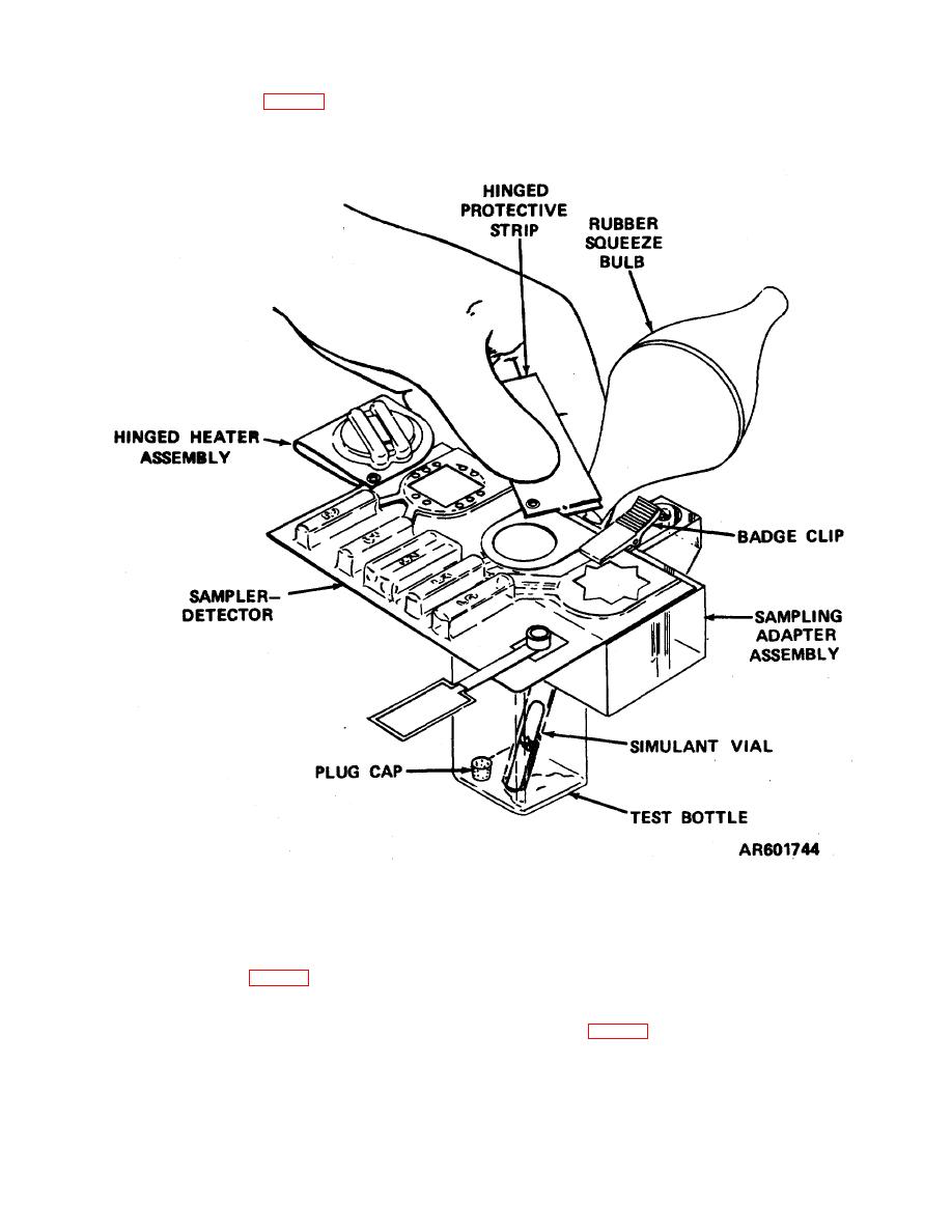
Figure 2-3. Holding the sampler-detector to the sampling adapter assembly ready for sampling. |
|
||
| ||||||||||
|
|
 TM 3-6910-227-10
k. Using the badge clip (fig. 2-3) on the sampling
side up and test spots over the oval opening) to the
adapter, fasten the sampler-detector (ampoule
sampler adapter.
Figure 2-3. Holding the sampler-detector to the sampling adapter assembly-
ready for sampling.
l.
Remove the screw cap from a previously
p. Remove the test bottle from the sampling
adapter. Replace the screw cap on the test bottle.
prepared test bottle. Screw the test bottle onto the
q.
Hold the sampler-detector by the hinged
sampling adapter assembly (fig. 2-3).
m. Hold the sampler-detector tightly to the sampling
protective strip.
r.
Finger-crush the second green ampoule
adapter assembly with one hand. Pump the rubber
(marked 4) (fig. 2-2). Swing the hinged heater assembly
squeeze bulb ten times using the other hand.
over the test spot. Vent vapor away from operator's
n. Remove the sampler-detector from the sampling
body. Leave the hinged heater assembly in place for 1
adapter assembly.
minute.
o. Hold the lewisite tablet rubbing tab with the tablet
s. Swing hinged heater assembly (after 1 minute
mark (step c above) over the sampling adapter bottle
has passed) away from test spot.
opening. Pump the rubber squeeze bulb 10 times
2-5
|
|
Privacy Statement - Press Release - Copyright Information. - Contact Us |
