 |
|||
|
|
|||
|
|
|||
| ||||||||||
|
|
 TM 3-4240-302-30&P-3
Section II TROUBLESHOOTING
2-5.
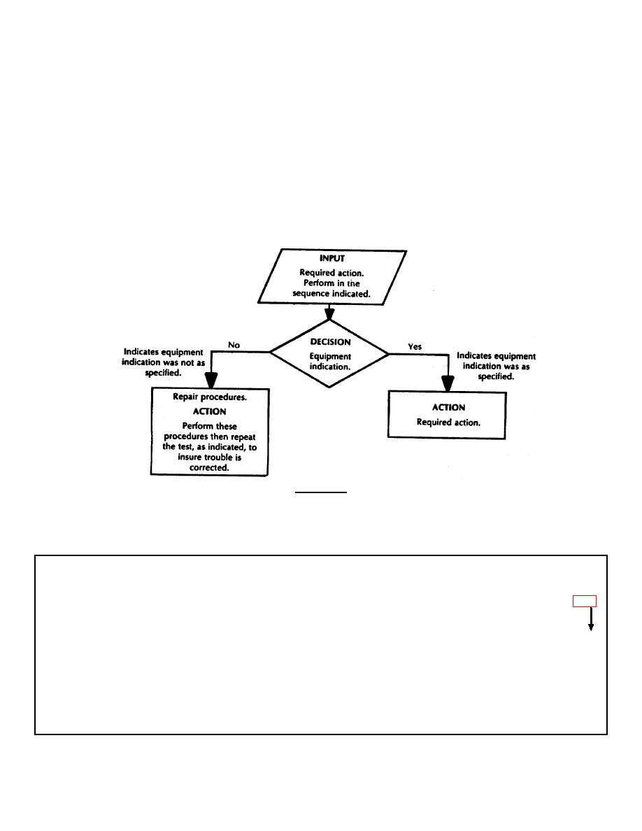
FLOW CHART PROCEDURES.
This
2-4. SCOPE. This section provides information for
locating and correcting problems in the collective
troubleshooting procedure is set up so that you actually
are performing a module functional checkout. For
protection equipment. Use the following flow charts to
example, if you have a good protective entrance control
isolate component problems and to locate repair
module (PECM), you perform only the functional
instructions.
checkout (yes path). If the PECM is defective (no path),
the procedure directs you step-by-step to locate a
defective component or a wiring problem. After module
repair, you repeat the functional checkout at the point in
the troubleshooting procedure where you originally
dropped out.
The following describes the
troubleshooting chart symbols.
WARNING
High voltage is used to power this equipment. Before removing or installing power cable, be
sure that POWER switch on control module is set to OFF and power source is shut down to
avoid personal injury or loss of life.
INDEX
PAGE
TROUBLESHOOTING PROCEDURE
PECM .................................................................................................................................................................. 2-3
TEST EQUIPMENT
Multimeter 6625-01-092-1197
Power Supply 6130-00-408-4962 (or equiv)
Differential Pressure Gage 6685-00-087-6331
Hypodermic: Syringe 6515-00-754-0412
Hose Tee 4730-00-082-5402
Tubing 4720-00-059-5819
Adapter 4730-00-782-5582
Resistor 100 ohm, 10 W
2-2
|
|
Privacy Statement - Press Release - Copyright Information. - Contact Us |
