 |
|||
|
|
|||
|
Page Title:
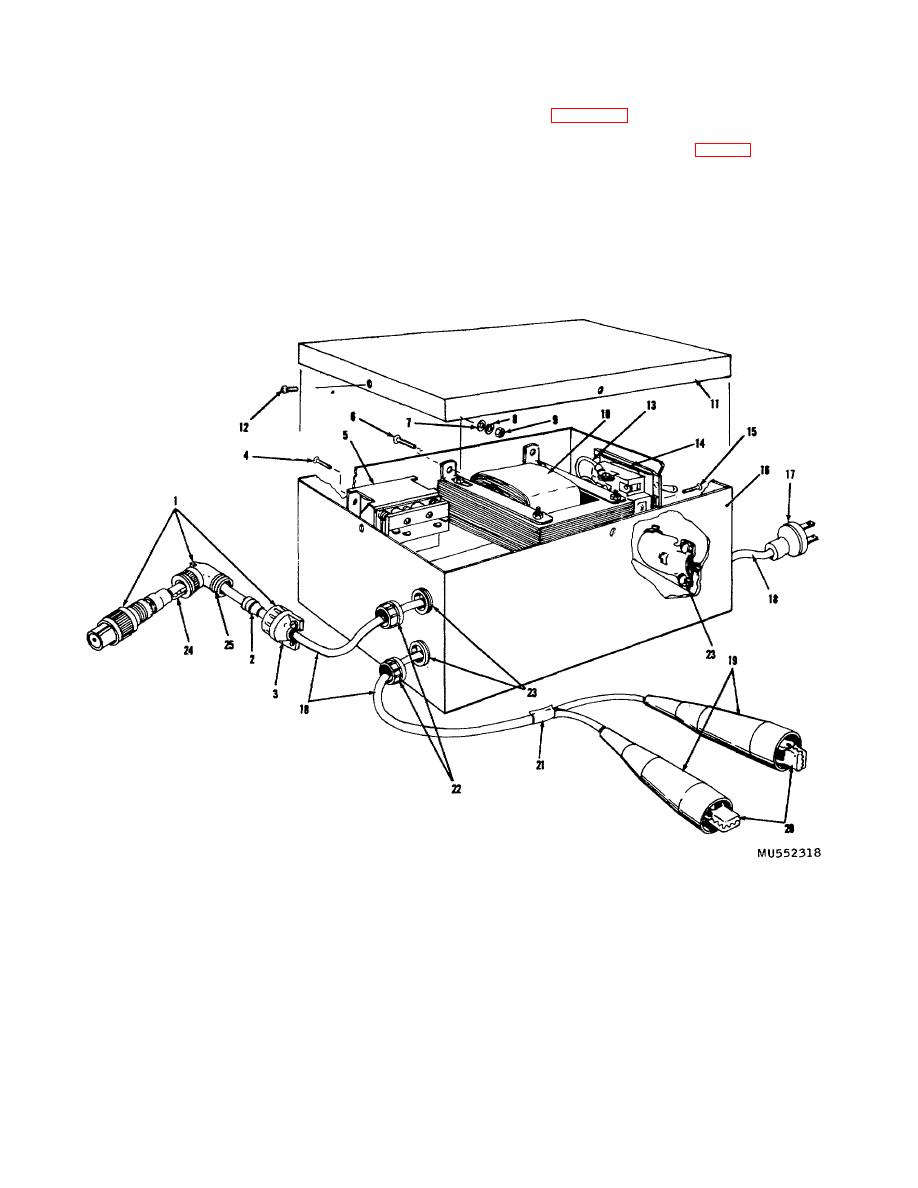
Figure 5-4. Transformer details. |
|
||
| ||||||||||
|
|
 TM 3-4240-201-13
b. Function. The function of the transformer is
the secondary winding output is 30 volts. The relay is a
double pole double throw relay that operates on 115 volts
shown in figure 1-6. When the toggle switch is turned
600 Hz ac. The toggle switch is a three pole single throw
on, the 115 volt ac power flows through the primary
switch. The three power cables are two conductor
winding of the transformer (10, fig. 5-4) and through the
rubber covered cables. Two power cables are 3 feet
armature of the relay (5), energizing the relay. The
long and the other is 6 feet long. The 115 volt ac power
secondary winding of the step down power transformer
cable has a plug connector. The 24 volt dc power cable
(10) supplies 30 volts ac power through the first set of
has two battery electrical clips and two cable nipples.
contacts in the relay, through the toggle switch (15), and
The cable nipples are made of plastic and are used to
through the air purifier power cable to operate the electric
insulate the electrical clips. The battery electrical clips
motor in the centrifugal fan assembly. If the 115 volt ac
are lead plated spring clips with terminals. The air
power source fails (or if this power is removed for any
90
purifier power cable has a electrical connector.
reason), current ceases to flow through
1
Electrical
plug
connector
9
Nut
19
Plastic electrical cable nipples
assembly
10 Step down power transformer
20
Battery electrical clip
2
Sleeving
11 Transformer cover
21
Plastic electrical insulation
3
Electrical connector cable
12 Machine screw
tape
clamp
13 Insulated electrical wire
22
Electrical conduit bushing
4
Machine screw (4 places)
14 Toggle switch
23
Electrical style box connector
5
Relay
15 Machine screw
24
Ground wire
6
Machine screw
16 Transformer case
25
90' housing of connector
7
Flat washer
17 Electrical plug connector
8
Lockwasher
18 Electrical power cables
Figure 5-4. Transformer details.
5-4
|
|
Privacy Statement - Press Release - Copyright Information. - Contact Us |
