 |
|||
|
|
|||
|
Page Title:
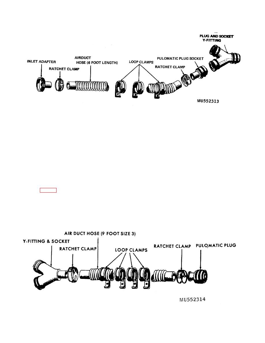
Figure 4-4. Size 2 hose assembly, exploded view. |
|
||
| ||||||||||
|
|
 TM 3-4240-201-13
Figure 4-4. Size 2 hose assembly, exploded view.
(b) Assembly is reverse of disassembly
excessive wear, and dry rot. Replace damaged parts as
((l)(a) through (d) above).
necessary.
(3) Assembly.
c. Size S Hose Assembly Repair. The following
(a) Place ratchet clamps on the ends of
procedures are for one size 3 hose assembly.
the hose. Insert a Y-fitting and socket and/or pulomatic
(1) Disassembly.
plug as required into hose. Tighten the ratchet clamps
(a) Remove the inlet adapter from the
using slip joint pliers. The teeth of the lock lever engage
headpiece.
the loop portion of the clamp when pliers are released.
(b) Remove the pulomatic plug from the
(b) Insert pulomatic plug end into the
Y-fitting and socket as required.
pulomatic socket in manifold assembly. Connect two
(c) Remove the damaged hose from
size 2 hoses to Y-fitting and socket end of the hose
the bed by removing the wood or machine screws and
assembly.
loop clamps (fig. 4-5).
(c) Install loop clamps as required on
(d) Use a sharp pointed tool and
each hose and fasten to bed using the wood/ machine
disengage the lock lever part of the ratchet clamp from
screws previously removed.
the teeth of the lock. Repeat this procedure to remove
ratchet clamps as necessary.
(2) Inspection. Inspect the ratchet clamps, Y-
fitting and socket, pulomatic plug, and hose for damage,
Figure 4-5. Size 3 hose assembly, exploded view.
4-6
|
|
Privacy Statement - Press Release - Copyright Information. - Contact Us |
