 |
|||
|
|
|||
|
Page Title:
CHAPTER 4 ORGANIZATIONAL MAINTENANCE INSTRUCTIONS |
|
||
| ||||||||||
|
|
 TM 3-4240-201-13
CHAPTER 4
ORGANIZATIONAL MAINTENANCE INSTRUCTIONS
Section I. SERVICE UPON RECEIPT OF MATERIEL
manifold assembly is equipped with airflow control caps
4-1.
New Materiel
on each pulomatic socket. See that the nameplate is
fastened to housing and that it is legible. See that
a. General.
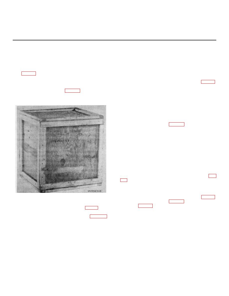
The filter unit is received by
pulomatic sockets are not out of round or damaged. See
organizational maintenance personnel packed in a wood
that external surfaces are painted white.
box (fig. 4-1). Open the wood box by cutting the metal
straps and removing the lid, taking care not to damage
c. Transformer. Unpack the transformer (fig. 1-5)
the contents. Unpack the filter unit from the box. Check
from its sealed container. Check the transformer case
the packing list against the contents of the box to insure
for damage. See that the 115 volt ac power cable and
that the filter unit is complete (fig. 4-2). Retain the box
plug are undamaged. See that the 24 volt dc power
with packing for future storage of filter unit or for moving
cable, red and black plastic cable nipples, and clips are
filter unit to another location.
undamaged. See that air purifier power cable and 90
connector are undamaged. Make sure that toggle switch
is in OFF position. See that case is painted white and
that markings are legible.
d. Hose Assemblies. Unpack the six size 2 and
two size 3 hose assemblies (fig. 1-3) from their boxes.
See that the size 2 and size 3 hose assemblies including
the hose connectors are undamaged.
e. Headpieces. Unpack the headpieces (fig. 12).
Check each headpiece and headpiece carrier for
damage. Check that there are six headpieces and six
headpiece carriers. Check each inlet adapter mount for
damage, missing gasket, and being out of round. See
that outlet valve disk is present.
f. Installation Instructions.
(1) Plug 2 each size 2 hose assemblies (fig.
hose assemblies.
(2) Plug the two remaining size 2 hose
assemblies into the loose plug and socket Y-fitting.
(3) Plug the plug and socket Y-fitting (fig. 1-3)
Figure 4-1. Filter unit, crated.
into the pulomatic socket (fig. 1-4) on the manifold
assembly (fig. 2-1).
b. Air Purifier. Unpack the air purifier (fig. 1-4) from
its sealed container. Examine the air purifier externally
for damage. Remove the manifold assembly (para 4-7)
and see that the gas and particulate filters are in place
and undamaged. See that electric receptacle connector
for purifier power cable is not damaged. See that
4-1
|
|
Privacy Statement - Press Release - Copyright Information. - Contact Us |
