 |
|||
|
|
|||
|
Page Title:
CHAPTER 3 MAINTENANCE INSTRUCTIONS |
|
||
| ||||||||||
|
|
 TM 3-4240-201-13
CHAPTER 3
MAINTENANCE INSTRUCTIONS
Section I.
PREVENTIVE MAINTENANCE CHECKS AND SERVICES
3-1.
General
3-2.
Preventive
Maintenance
Checks
and
Services
This section provides in table 3-1 the operator with a list
of services which must be performed at the intervals
prescribed. Intervals of maintenance are based on
provides a list of services that the operator must perform
normal operation and will be reduced or extended
either before or after operation.
Defects that are
depending on operating conditions. The filter unit will
discovered during preventive maintenance servicing
normally be used on very short notice. This equipment
must be corrected immediately. The number also
must be kept in a constant state of readiness.
indicates the sequence in which the service must be
performed.
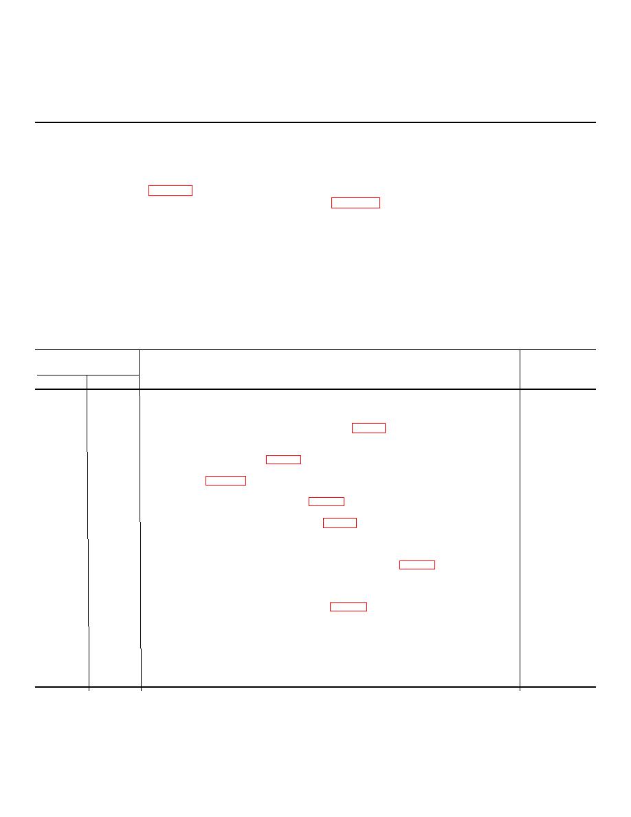
Table 3-1. Preventive Maintenance Checks and Services
B-Before operation
A-After operation
Time required: 1.1 hours
Time required: 1 hour
Interval and
Item to be inspected procedure
Work
Sequence No.
Time
B
A
(M/H)
1
9
Publication. See that a copy of TM 3-4240-201-13 is available and in serviceable con-
0.1
dition.
2
10
Overall Visual Inspection. See that the filter unit (fig. 1-1) is clean and all parts are
0.2
free of rust, pitting, corrosion, and dry rot. See that none of the components are
missing or damaged.
3
11
Air Purifier. Check housing (fig. 1-4) for dents and loose connections. Notify organi-
0.1
zational maintenance to replace gas filter and particulate filter when they become
contaminated (table 2-1). See that airflow control caps are in place and in good
condition.
4
12
Transformer. Check transformer case (fig. 1-5) for damaged, loose, or missing cables,
0.1
damaged connectors, loose or missing screws, and broken toggle switch.
5
13
Battery. Check electrolyte level in battery (fig. 1-1) cells visually. Maintain liquid
0.1
level in battery cells by adding distilled water as necessary. Clean the terminals and
remove corrosion. See that protective cable nipples cover both clips of the 24 volt dc
power cable.
6
14
Hoses. See that hoses are routed according to the diagram (fig. 2-1). See that hoses
0.2
are not stretched or sharply bent. See that loop clamps are used to support hoses along
their lengths. Check ratchet clamps, inlet adapter, pulomatic plug, and Y-fittings for
damage.
7
15
Headpiece and Carrier. Check headpieces (fig. 1-2) for cleanliness, holes, and loose
0.2
or cracked plastic material. See that inlet adapter mount, strap, and outlet valve are
not damaged. Check for missing carriers.
8
16
Operational Check. Move toggle switch to ON position to see that it operates. Remove
0.1
115 vac power cable from ac power source to see that it automatically transfers to
dc power source. If it is satisfactory, place toggle switch to OFF position. Plug the
115 vac power cable in to the power source.
3-1
|
|
Privacy Statement - Press Release - Copyright Information. - Contact Us |