 |
|||
|
|
|||
|
Page Title:
Pressure Regulator |
|
||
| ||||||||||
|
|
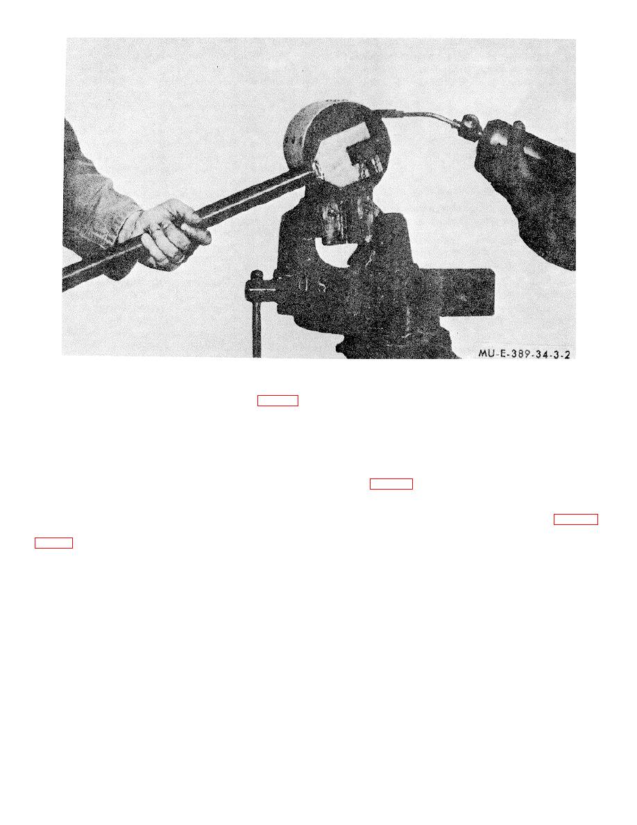
 Figure 3-2. Pressure tank & pressure tank valve.
a. Removal.
(2) Screw a check valve assembly (18, fig. 2-5)
to the side of the pressure tank valve (17) and tighten.
(3) Screw a plug assembly (14) to the bottom of
(1) Remove the pressure tank and valve
the pressure tank valve (17) and tighten.
assembly. Refer to TM 3-1040-214-12.
(2) To gain access to the pressure regulator,
e. Charging and Testing Pressure Tank.
remove one cord attaching the carrier pack to the frame.
(3) Disconnect the quick-disconnect coupling
Charge and test the pressure tank for leaks (TM 3-1040-
half (3, fig. 2-6) on each hose assembly.
221-12).
(4) Hold the pressure regulator (14) and
f. Installation.
disconnect the diffusion tube nut (6) from the adapter (7).
(5) Remove the tube assembly (11, fig. 3- 3)
and adapter (7).
(1) Connect the open end of the valve shaft (6,
(6) Unscrew the safety valve and nipple (21)
from the pressure regulator.
(2) Connect the nut (12) that is on the valve shaft
(7) Loosen the spring retaining plug (17) and
(6) to the pressure tank valve.
remove it slowly to prevent the spring (15) from popping
(3) Install the pressure tank to the agent tanks.
out of the cavity.
Refer to TM 3-1040-214-12.
(8) Remove the preformed packing (16), spring
(15), strainer (13), seal retainer (12), washer (10), seal
3-4. Pressure Regulator
(9), valve seat (8), gasket (18), and push rod (19).
(9) Remove eight screws (20). Slowly separate
Genera! support maintenance personnel are authorized
the pressure regulator body (6) from the dome (1) to
to replace the diaphragm, springs, strainer, valve
prevent losing the compression spring (5).
adapters, and related hardware.
3-4
|
|
Privacy Statement - Press Release - Copyright Information. - Contact Us |