 |
|||
|
|
|||
|
Page Title:
|
|
||
| ||||||||||
|
|
 TM 11-7010-207-23
TECHNICAL
PRINCIPLES
OF
OPERATION
various transmission lines to send and receive data.
Two converters of the same type are required for data transmission between two data
terminals. The two terminals can be central processors, or a central processor and
a remote terminal. The communications link between the two converters must be
dedicated metallic circuits or direct connected phone lines. Interface connections
to DTE and DCE are povided bv the line and terminal connectors on the rear panel
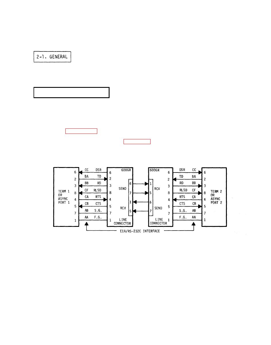
of each unit. Figure 2-1 illustrates the interface cabling. The interface `is
compatible with RS-232-C and MIL-188-114 low level input/output interface and
interface exchange requirements. Table 2-1 lists and describes each interface
signal.
4 WIRE/FULL OR HALF DUPLEX
DTE, DCE Interface
The transmit portion of each converter begins carrier transmission when Request to
Send (RTS) turns on. Transmit data from the terminal or data communications
equipment is inhibited in a mark state until the converter has timed out the Clear
to Send (CTS) delay. After CTS turns on, the terminal may begin transmitting the
normal rate. When a converter is operating in a full-duplex mode, the transmitter
is controlled by RTS and the received data is controlled by Received Line Signal
Detector (RLSD). When transmitting in half-duplex mode, the transmitter and
receiver are controlled by logical combinations of RTS and RLSD. While
transmitting, receive data to the terminal is inhibited. If there is an attempt to
transmit and receive simultaneously, the first function to occur will inhibit the
other.
|
|
Privacy Statement - Press Release - Copyright Information. - Contact Us |