 |
|||
|
|
|||
|
|
|||
| ||||||||||
|
|
 TM 11-7010-207-23
Operating environment:
Temperature: 32F to 122F (OC to 50C)
Relative humidity: O% to 90% (noncondensing)
Converter assembly electrical requirements:
Voltage: 92 V ac to 130 V ac
50 to 400 Hz
Interface circuit requirements:
RS-232-C and MIL-188-114
Line Requirements:
Unloaded dedicated metallic pairs, 19 to 26 gauge
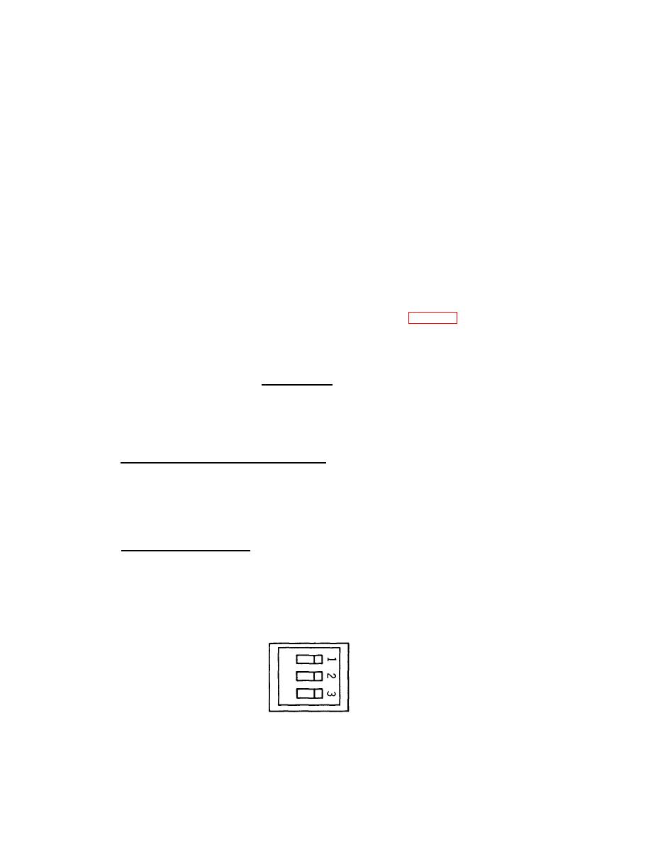
When the mechanical installation has been completed, various strap-selectable
configurations must be set before the electrical installation can be completed.
Strapping is accomplished by setting DIP switch S2 (fig. 1-4). Switch S2 is on the
right center section of each rack-mounted converter board. See your system manual
for the switch position settings required for your system. An explanation of each
switch position is as follows:
a. RTS/RTS ON(S2-1). Switch S2-1 determines if Clear-to-Send
(CTS) is
RTS ON position,
controlled by Request-to-send (RTS) or is on continuously. In the
er Mode, and CTS
CTS is ON and the converter board is placed into the Constant Carri
is on continuously. The RTS ON position is used when the attached
terminal does
Request-to-Send.
not supply an RTS signal. In the RTS position CTS is controlled by
b. Constant/Switched Carrier (S2-2). In the CONSTANT CARRIER position, S2-2
configures the converter board to operate in a constant carrier mode. In this mode
the converter's transmitter is always on. In the SWITCHED CARRIER position, S2-2
configures the converter board to operate in a Switched carrier mode. In this mode
the converter's transmitter is controlled by RTS. The SWITCHED CARRIER position is
over-ridden when S2-1 is in the RTS ON position.
c. RTS/CTS Delay (S2-3). Switch S2-3 selects either a 16 or 50 msec delay
between the time that RTS goes on and CTS is turned on.
S2
ON
OFF
RTS ON
1 RTS
2 SWITCHED CARRIER
CONSTANT CARRIER
3 16 ms RTS TO CTS DELAY
50 ms
Configuration DIP Switch S2
1-7/(1-8 blank)
|
|
Privacy Statement - Press Release - Copyright Information. - Contact Us |
