 |
|||
|
|
|||
|
Page Title:
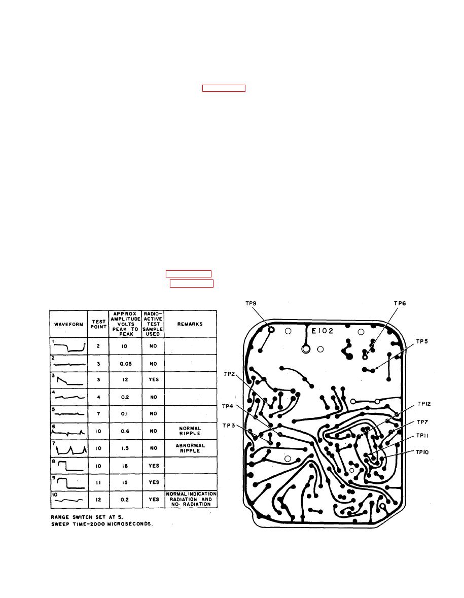
Figure 2-2. WAVEFORM DIAGRAM AND TEST POINT LOCATIONS. |
|
||
| ||||||||||
|
|
 TM 11-6665-209-40
Test equipment and tools required: Table 2-1 below lists the tools and test equipment
required for troubleshooting and repair of the radiac set at general support maintenance.
NSN
NOMENCLATURE
M u l t i m e t e r TS-352B/U
V o l t m e t e r , Electronic ME-30A/U
Oscilloscope OS-8/U (or equivalent)
6625-00-699-0263
Test Set, Electronic Tube TV-2/U
Test Set, Transistor TS-1836D/U
6625-00-179-9037
Calibrator Set, Radiac AN/UDM-2
Tool Kit, Electronic Equipment TK-105/U
a. Waveforms shown in figure 2-2 are normal waveforms, unless otherwise noted.
b. Test points shown in figure 2-2 are located on the printed circuit board. Ensure
that good contact has been made when making waveforms and voltage measurements.
|
|
Privacy Statement - Press Release - Copyright Information. - Contact Us |
