 |
|||
|
|
|||
|
Page Title:
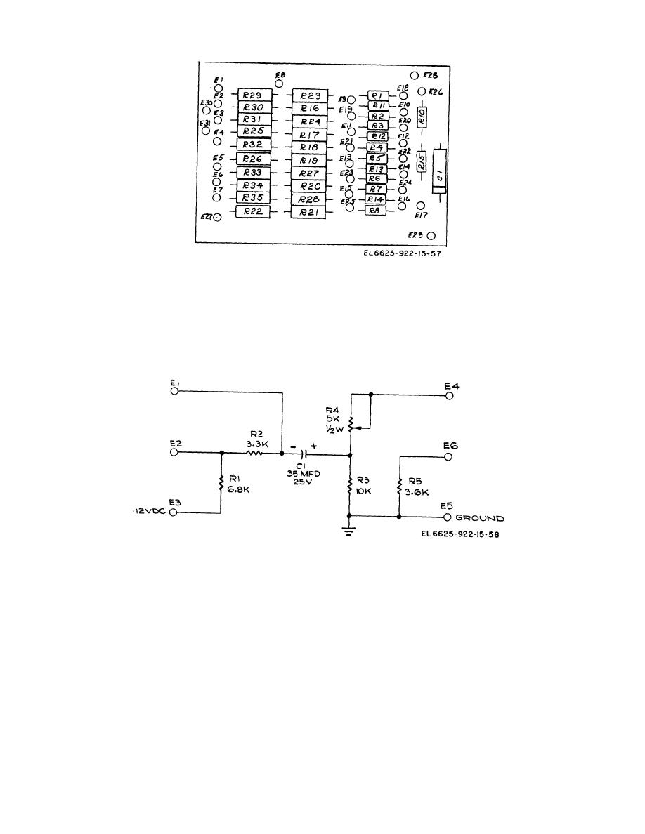
Figure 9-41. Meter modulation adjust (A20), B-4806, Schematic diagram |
|
||
| ||||||||||
|
|
 TM 11 6625-922-15
Figure 9-40. Receive impedance selector and attenuator
(A18), C-4714, location of components.
NOTE:
UNLESS OTHERWISE SPECIFIED
RESISTORS ARE 1/4 W, 5%
Figure 9-41. Meter modulation adjust (A20), B-4806, Schematic diagram
|
|
Privacy Statement - Press Release - Copyright Information. - Contact Us |