 |
|||
|
|
|||
|
|
|||
| ||||||||||
|
|
 TM 11-6625-922-15
Step
Condition
Requirement
15 Connect leads of AN/USM-223 betweenrear
Dc level on AN/USM-223 will vary from 1 to approxi-
panel analog frequency output terminal
mately 5 volts
MIT FREQUENCY-RECEIVER-FRE-
QUENCY switch to TRANSMIT FRE-
QUENCY and SWEEP CARRIER-REFER-
ENCE switch to CARRIER. Operate CAR-
RIER FREQUENCY control and RANGE
(KHZ) switch to vary output carrier fre-
quency from 0.100 KHz to 552 kHz as
monitored on the FREQUENCY display.
16 Connect leads of AN/USM-223 between
DC level on AN/USM-223 will vary from 0.5 to ap-
rear panel analog amplitude terminal (fig. 3-2)
proximately 2.3 volts.
and ground. Operate % MOD-RECEIVE
LEVEL TRANSMIT LEVEL switch to
TRANSMIT LEVEL, RANGE (KHZ) switch to
.1 -50, and operate CARRIER FREQUENCY
control to obtain an indication of 1,000 Hz on
the FREQUENCY display. Operate the
TRANSMIT LEVEL DBM control from fully cw to
fully ccw.
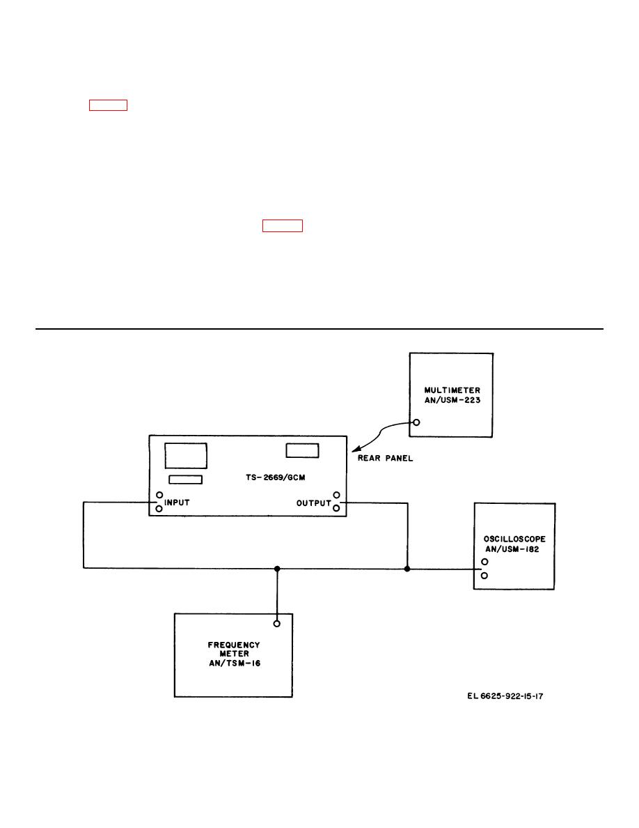
Figure 6-1. Test setup.
6-6
|
|
Privacy Statement - Press Release - Copyright Information. - Contact Us |